Appendix A
Configuration Fundamentals
The basic setups in this section can be thought of as the building blocks of an E1500system configuration. More complicated system setups generally depend upon these fundamental configurations.
Fundamentals A: SIM card installation
Initial setup of the unit requires SIM card installation prior to powering up. This section describes SIM card installation. SIM cards slots are a nano SIM 4FF form factor.
Tools Needed
T10 Torx bit
Tweezers
OPENING THE UNIT
Opening the Unit
Opening The Unit
Unscrew the four (4) corner screws and lock washers from the unit's rear panel.
Remove the rear panel and locate the SIM slots on the left side of the upper circuitboard. When viewed from the back, Slot 1 is on the left, Slot 2 is on the right.
Figure 92. Rear Panel Removal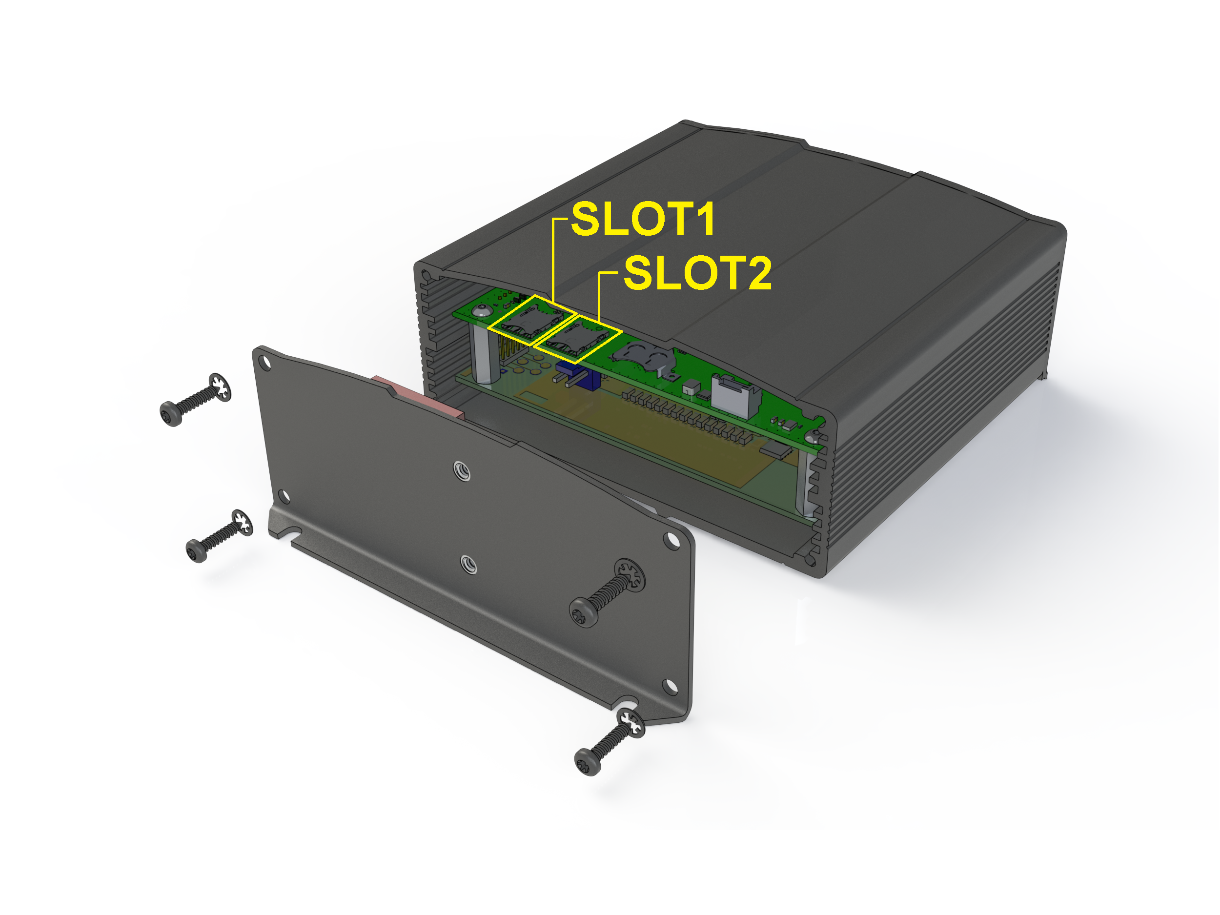
Installing SIM Cards
Using tweezers, insert the SIM cards in slots 1 and 2.
Figure 93. SIM Card Insertion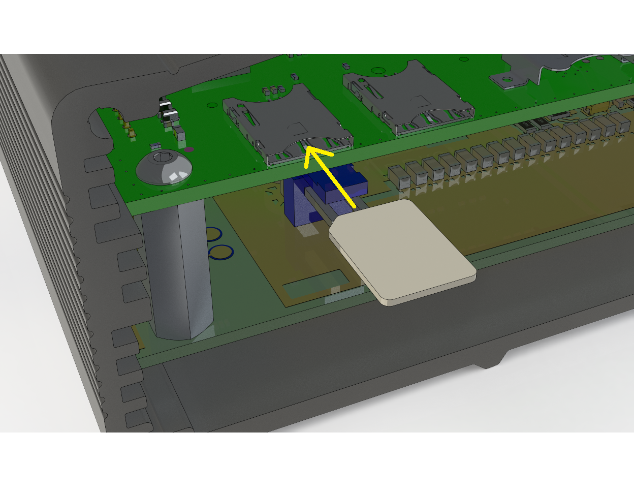
Closing the Unit
Replace the rear panel and reattach corner screws and lock washers.
For details regarding setting up SIM cards, See Web Admin, Step 6
Removing SIM Cards
A 'pick' of sorts is needed to remove SIM cards that have previously been installed. Any type of pick with a 90-degree bend at one end should suffice. Gently hook the pick onto the back edge of the SIM card and pull the card out enough to remove it with tweezers.
Fundamentals B: LAN Interface config
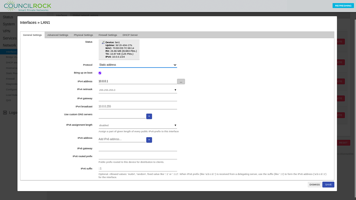
To set up the E1500 LAN interface according to your network plan, interface settings are accessed via the Network > Interfaces menu, by clicking on the EDIT button on a LAN interface and selecting the General tab. The LAN interface status is displayed in a highlighted box, showing the Device name, uptime, MAC address, Total received/transmitted packets (TX/RX), and the IP Address in CIDR notation. The following fields are available for user input:
Protocol: Static or Dynamic
Bring up on boot - checkbox option to start the interface when the unit boots up.
IP Address (IPV4 and IPV6)
Netmask (IPV4)
IPV4 Broadcast address
Gateway address (IPV4 and IPV6)
Custom DNS server settings
IPV6 Assignment length, routed prefix, suffix
 |
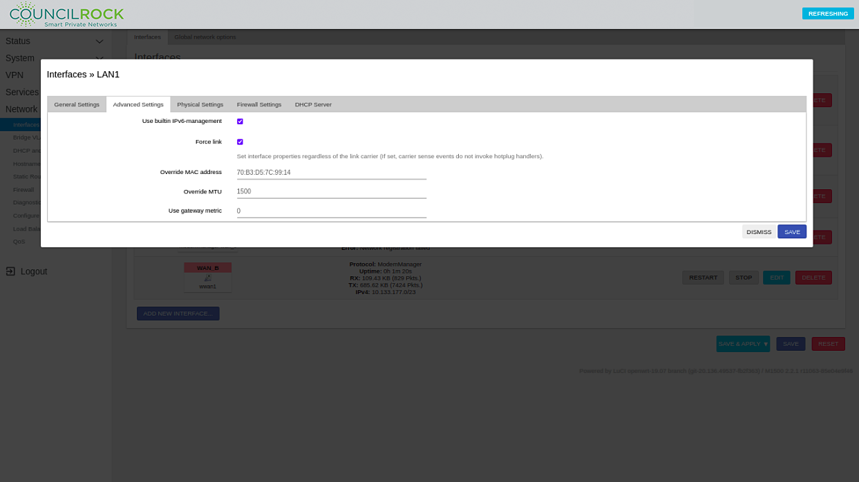
The Interfaces >> LAN > Advanced Settings menu has settings for:
Using built-in IPv6 Management
Force link (to ignore carrier sense events)
Overriding the unit’s MAC address
Overriding the default Maximum Transmission Unit (MTU) - packet size
(for advanced users only - we recommend the default MTU setting)
Using a gateway metric - Gateway metric is a value assigned to an IP route for a network interface that identifies the cost associated with using that route. If the device has two routes to the same destination, the route with the lower metric will be preferred. The default value of 0 is usually the recommended setting for the LAN interfaces as the routes advertised by the LAN are usually “connected” routes.
Note
Built-in IPv6 management enables IPv6 prefix delegation for cases of IPv6 traffic tunneling over IPv4 networks.
 |
Verify the LAN is always in the LAN firewall zone on the Network > Interfaces >> LANx > Firewall Settings menu. For more, see Fundamentals C: WAN Interface config
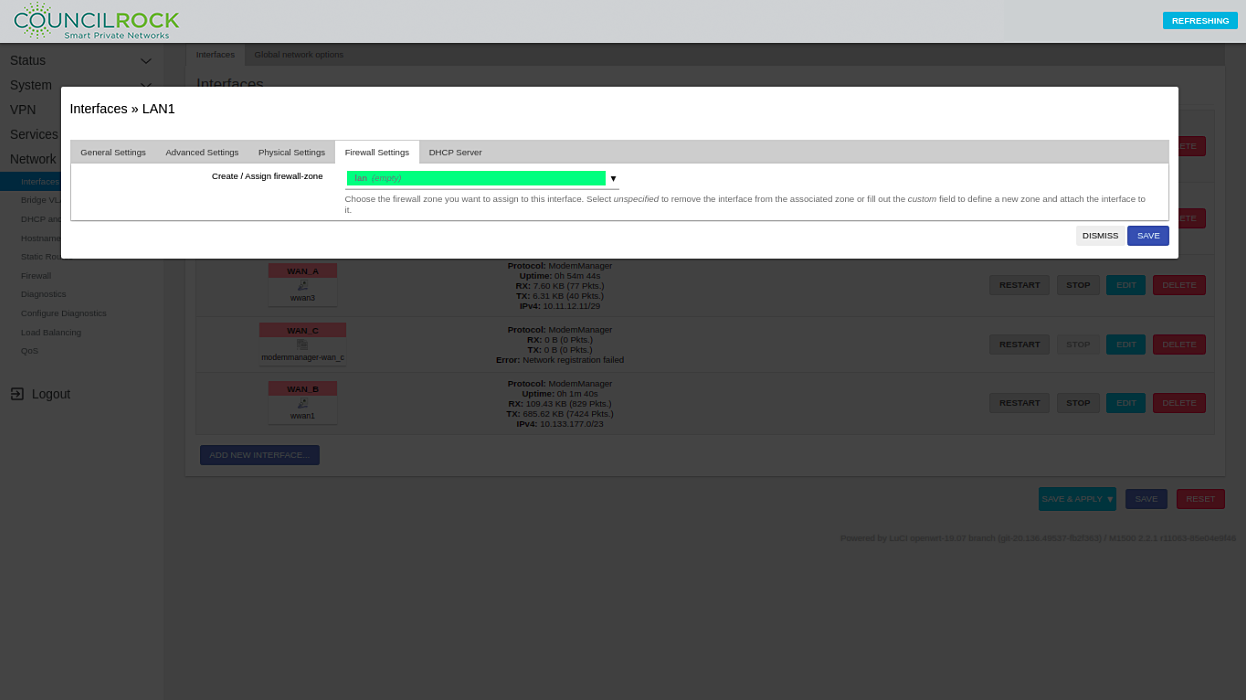 |
Your network deployment settings will vary from the example screenshots shown here (mainly IP addressing schemes / netmasks / gateways, but may also include settings such as bridging, firewalls, and DHCP servers). Enter your specific network details on each applicable menu tab and click Save.
Fundamentals C: WAN Interface config
To set up the WAN interface according to your network plan, Interface settings are defined via the Interfaces menu, by clicking on the EDIT button on a WAN interface and selecting the General tab. The WAN interface status is displayed in a highlighted box, showing the Device name, Uptime, Total received/transmitted packets (TX/RX), and the IP Address in CIDR notation.
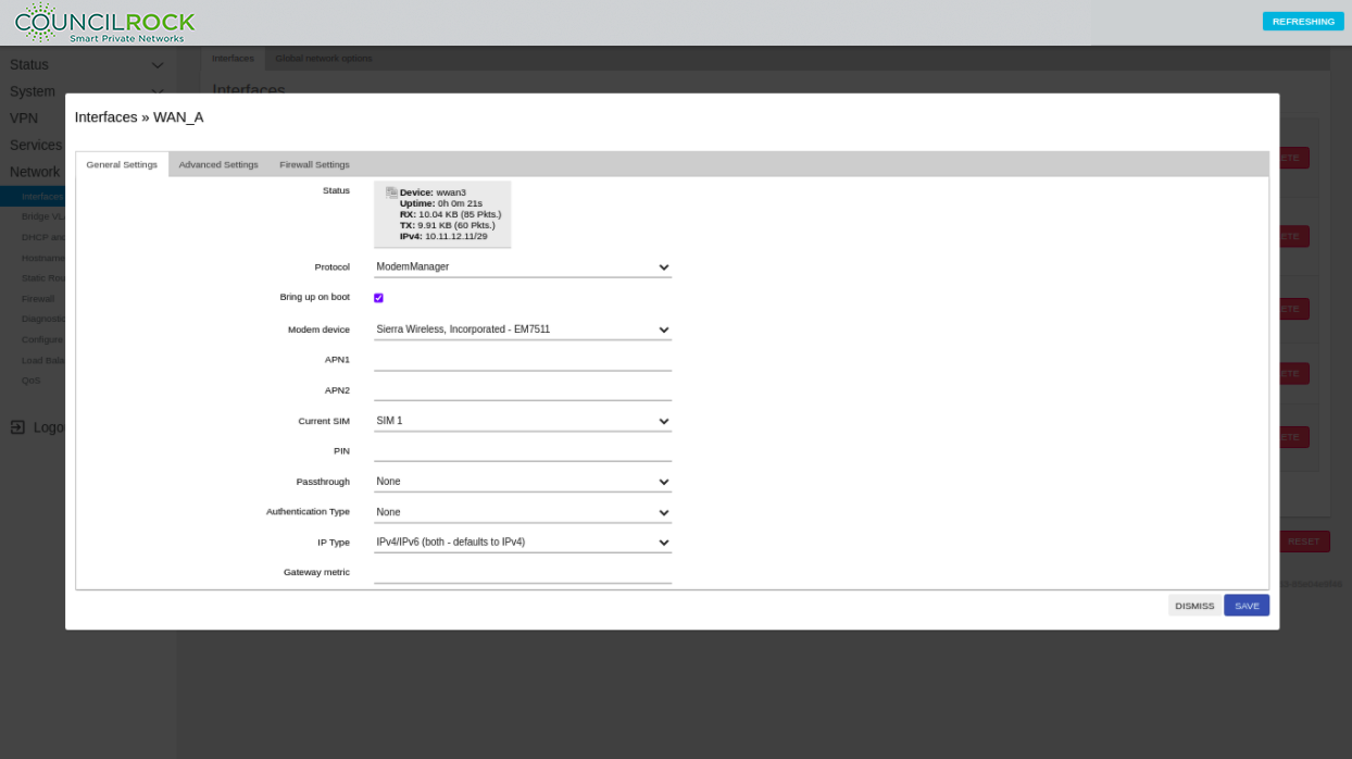 |
The following fields are available for user input:
Protocol - Defines how the device communicates with the LTE modem. Modem Manager is the recommended protocol option for all modems
Bring up on boot - checkbox option to start the interface when the unit boots up
Modem device - Defines which LTE modem is associated with the interface. Default selection is the recommended setting for general use
APN - Access Point Name. The defined APN for your network provider
Current SIM - Defines which SIM to use for dual SIM modems
PIN - for PIN protected SIM cards
Passthrough - Shares WAN IP address with a single device on the LAN. If WAN is set to Passthrough, the LAN interface should be set as "Static IP Address"
Authentication - Defines authentication methods with the WAN network provider (if required)
IP Type - (IPv4 / IPv6)
Gateway metric - In networks where multiple WAN interfaces are configured as default gateways, the Gateway metric determines which default gateway will be utilized. In these multiple default gateway networks, the default gateway with the lowest Gateway metric is used
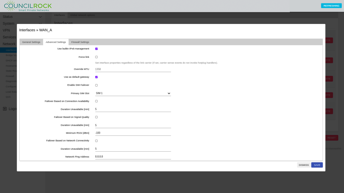
The Advanced Settings tab has settings for:
Using built-in IPv6 management
Force link (to ignore carrier sense events)
Overriding the default Maximum Transmission Unit (MTU) - packet size (for advanced users only - we recommend the default MTU setting)
Using the unit as a default gateway
Failover settings (See Use Cases)
Note
"USE AS DEFAULT GATEWAY" - Checking this box sets the interface as the outgoing node for any packet whose destination IP is not on the routing table. A user may configure multiple default gateways. However, be sure to give them different metrics using the Advanced Setting "Gateway metric." The device will use the default gateway with the lowest metric.
 |
Verify the WAN is always in the WAN firewall zone on the Interfaces >> WAN_x > Firewall Settings menu. (See also Use Case C: Firewall Rules)
Note
A zone can be configured to any set of interfaces but generally there are at least two zones for the sake of simplicity: lan for the collection of LAN interfaces and wan for the WAN interfaces. In most cases users generally want to allow/prevent the same type of traffic in & out of the LAN/WAN interfaces therefore it makes sense to group interfaces of the same type in the same zone.
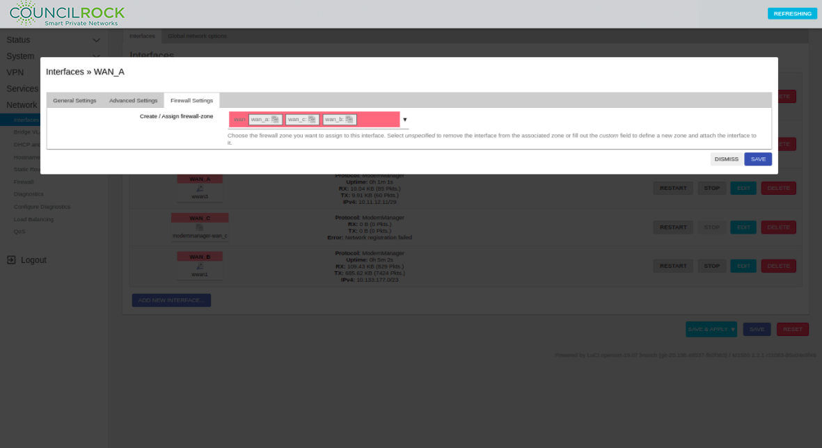 |
Your network deployment settings will vary from the example screenshots shown here (mainly IP addressing schemes / netmasks / gateways, but may also include settings such as bridging, firewalls, and DHCP servers). Enter your specific network details on each applicable menu tab and click Save.
Fundamentals D: System Administration
This section covers basic and advanced system administration topics.
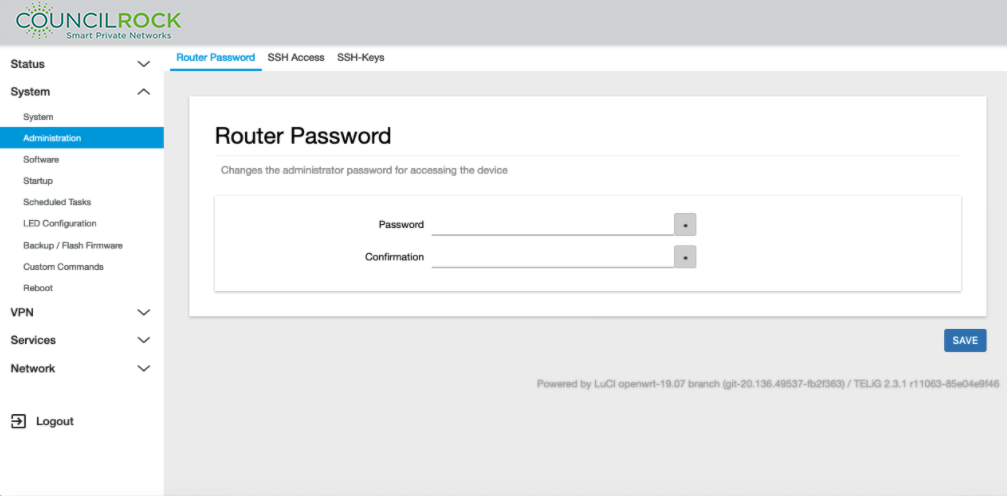
Changing Passwords
The password for the device can be changed by navigating to System > Administration > Router Password.
The password policy is:
Length: minimum 18 characters
Requirements:
1 lowercase letter
1 uppercase letter
1 number
1 special character
 |
Warning
The following topics are intended only for Advanced Users
Remote System Logging Configuration
Allows the user to configure the unit to send logs to an external syslog server.
By default, system logs are stored locally as a text file continually updated during system events. The System > System: Logging menu allows the user to specify logging parameters, detailed below. The amount of system log entries, and therefore the rate at which the log is updated is determined by the log output level, which is selected on this screen under Log output level. For external log servers, setting up the server’s config files to receive logging data (passed by TCP/UDP) is an advanced user topic.
For more information, see https://openwrt.org/docs/guide-user/base-system/log.essentials
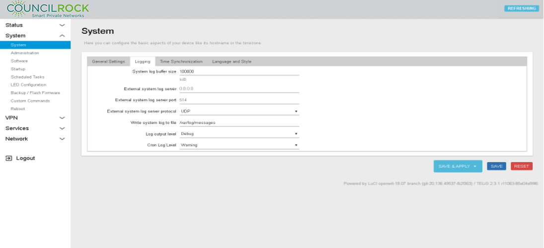 |
System log buffer size: Specifies how much memory to allocate for saving logs in the unit. When allocated memory is used up, the system will overwrite old messages.
External system log server: The IP address of the syslog server that the logs will be sent to.
External system log server port: The transport layer port of the syslog server that the logs will be sent to.
External system log server protocol: The transport layer protocol that will be used to send syslog messages to the external server.
Write system log to file: local directory in the device where the syslog messages will be stored. Leave as default value.
Log output level: Syslog logging level. Levels are shown in the dropdown list in order from least to most important. Thus, for a minimal log, select “Error” level or higher. For a more verbose log, select “Warning” or lower level.
Cron Log Level: Logging level for Cron jobs. Selections are “Debug”, “Normal” and “Warning”. For a verbose Cron log, select “Debug”. For a minimal Cron log, select “Warning"
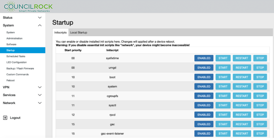
Disabling Unused Services
To disable scripts for services that are executed automatically when the unit powers up, navigate to System > Startup. Here you can disable the desired scripts. This feature is intended only for advanced users.
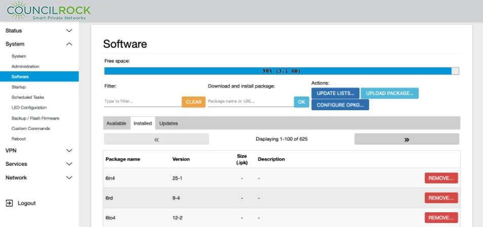
Uninstalling Unused Packages
To uninstall packages from the unit, navigate to System > Software. Click on “update list” to fetch the packages installed in the unit and then go click the “Installed” tab. Here you can remove unwanted packages. This feature is intended only for advanced users.
 |
 |