Settings and Web Admin Interface
Overview
The unit settings are managed through the Web Admin Interface, accessible through a web browser as described in Initial Setup. The unit settings are grouped by function as follows:
STATUS
SYSTEM
VPN
SERVICES
NETWORK
Menus are organized by function in the left sidebar. Submenus for each function are accessible via Tab headings in the main window.
STATUS
The Status menus display current System Status Overview and status details of Firewall / LTE / GPS / Routing / Logging / Processes / Load Balancing. Real-time graphs of system performance are available here as well. Status menus are useful for gathering system info and/or troubleshooting. User input is generally not expected on the Status menus. Each menu is summarized in the following subsections.
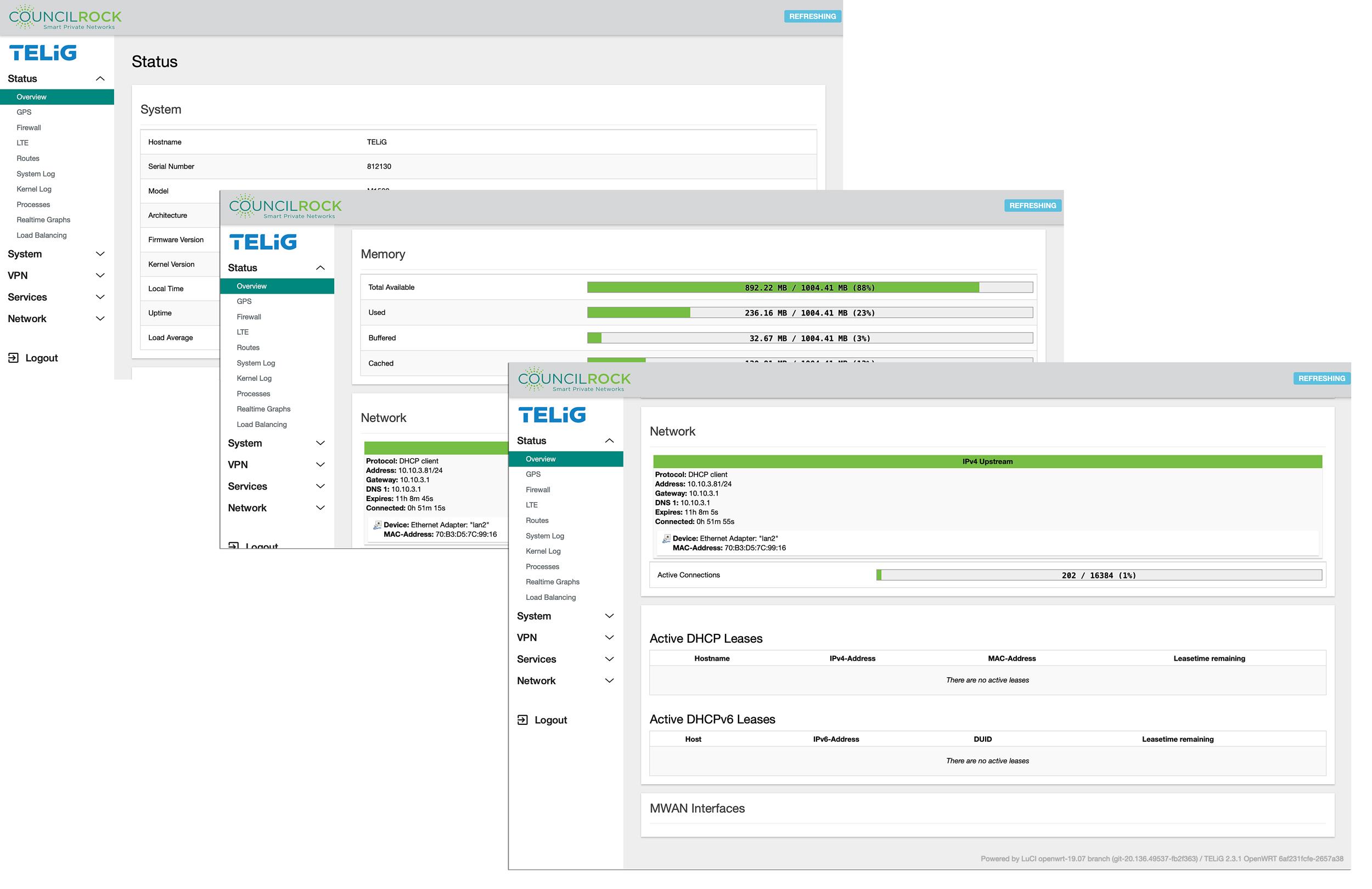
Overview
The System Status Overview displays system information regarding hardware including serial number, model, and software version as well as memory utilization and network connection information - IP/DHCP info for the active network, active DHCP leases, and Multi-Wide Area Network (MWAN) interfaces.
 |
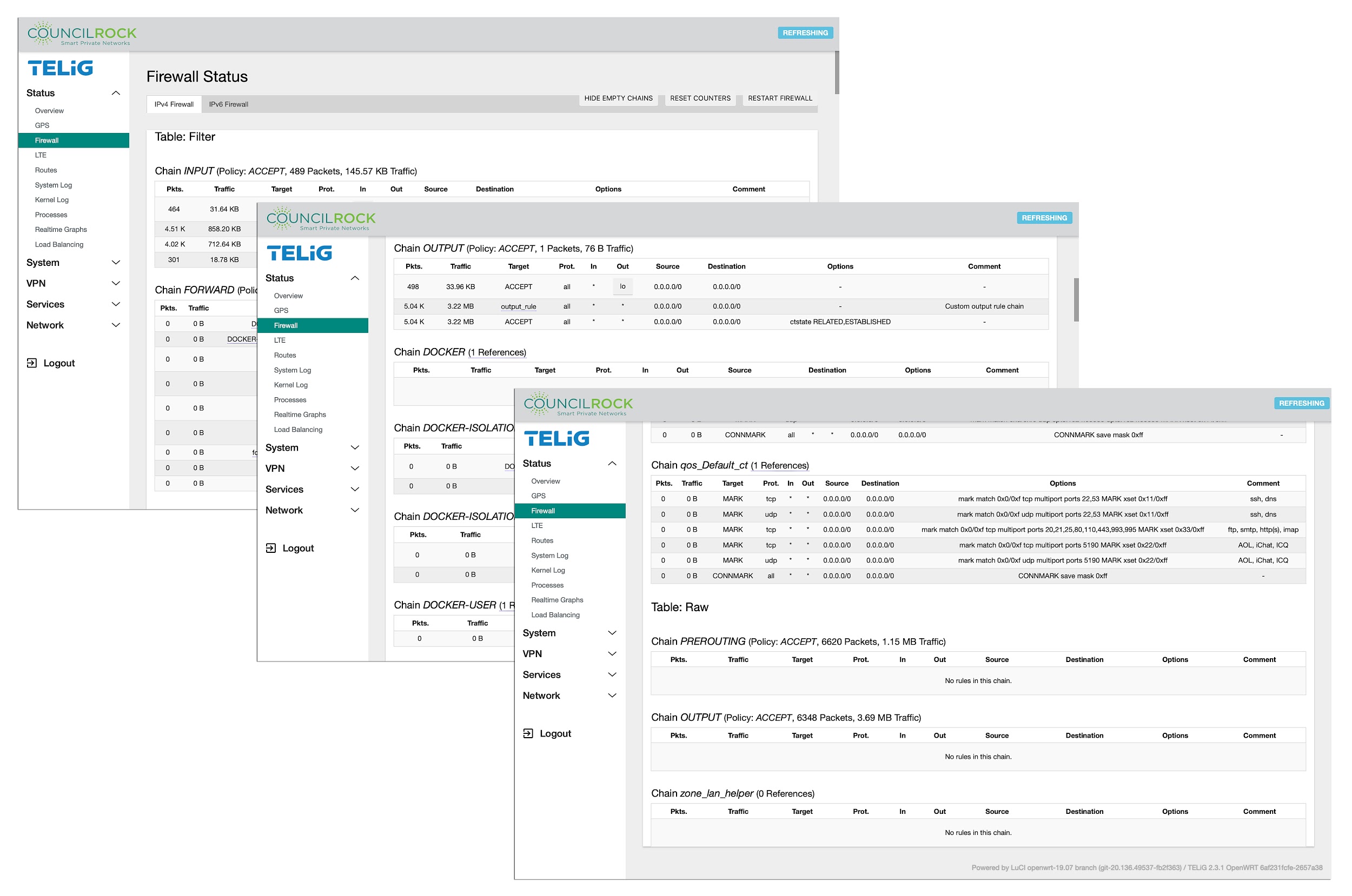
Firewall
A complete list of active Firewall rules is displayed in this menu, with real time data regarding network traffic handled by these rules.
IPV4 and IPV6 are separately displayed by selecting the Tab at the top of the main window.
Firewall rules are shown at the WAN and LAN level for Inputs, Outputs, Forwarding, Rejection, and Quality of Service (QoS). Rules are sorted into Tables by FILTER / NAT / MANGLE / RAW. Firewall NAT tables apply to IPv4 only.
Each rule entry describes the rule via the target, protocol, input interface, output interface, source IP address or IP address range, and destination IP address or IP address range. Each rule entry also displays options and comments, if any. Finally, each rule entry displays the number of packets and amount of traffic handled by the rule.
Buttons at the top right of the screen allow the user to
Hide emtpy chains: removes chains with no firewall rules from the display
Reset Counters: sets all traffic counters to zero
Restart Firewall: restarts all firewall rule chains
 |
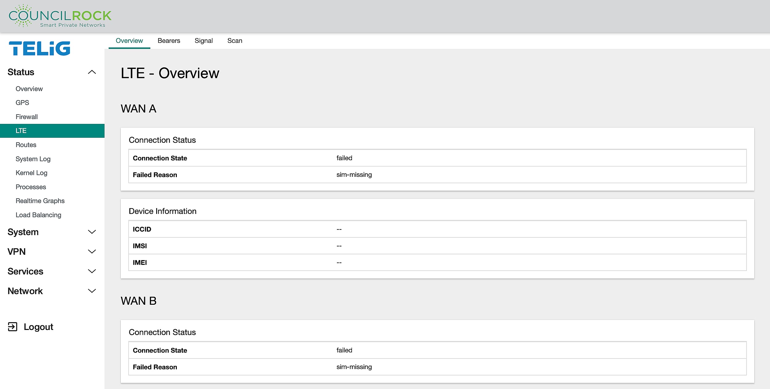
LTE
Displays information on the state of LTE modems and connections.
Submenus are accessible at the top of the LTE menu for displaying an overview of LTE WAN connections, LTE Bearers, LTE Signal indicators, and a scan tool for troubleshooting.
The Overview tab provides connection status for each modem present, including connection state, registration state, operator information, and signal quality as a percentage,as well as device information for each modem present, including Integrated Circuit Card Identifier (ICCID), International Mobile Subscriber Identity (IMSI), and International Mobile Equipment Identity (IMEI).
Connection States - LTE modem is:
Enabled: not connected to the cellular network
Connected: connected to the network provider
Connecting: attempting to activate the connection to the network provider
Disconnecting: deactivating the connection to the network provider
Disabled: not enabled and is powered down
Registration States - LTE modem is:
Registered: registered with network provider; data connections may be available for use
Idle: not registered, not searching for a new network provider to register with
Searching: not registered, searching for a new network provider to register with
 |
Signal Quality is shown as a percentage in the range from 0-100%, where higher percentage indicates better signal quality. Signal quality is based on the LTE radio’s RSSI level. In general, signal quality above 40% is usable.
The Bearers tab provides information on each LTE bearer network established for each modem present, including interface status, IPv4 and/or IPv6 network information, and data transmission statistics.
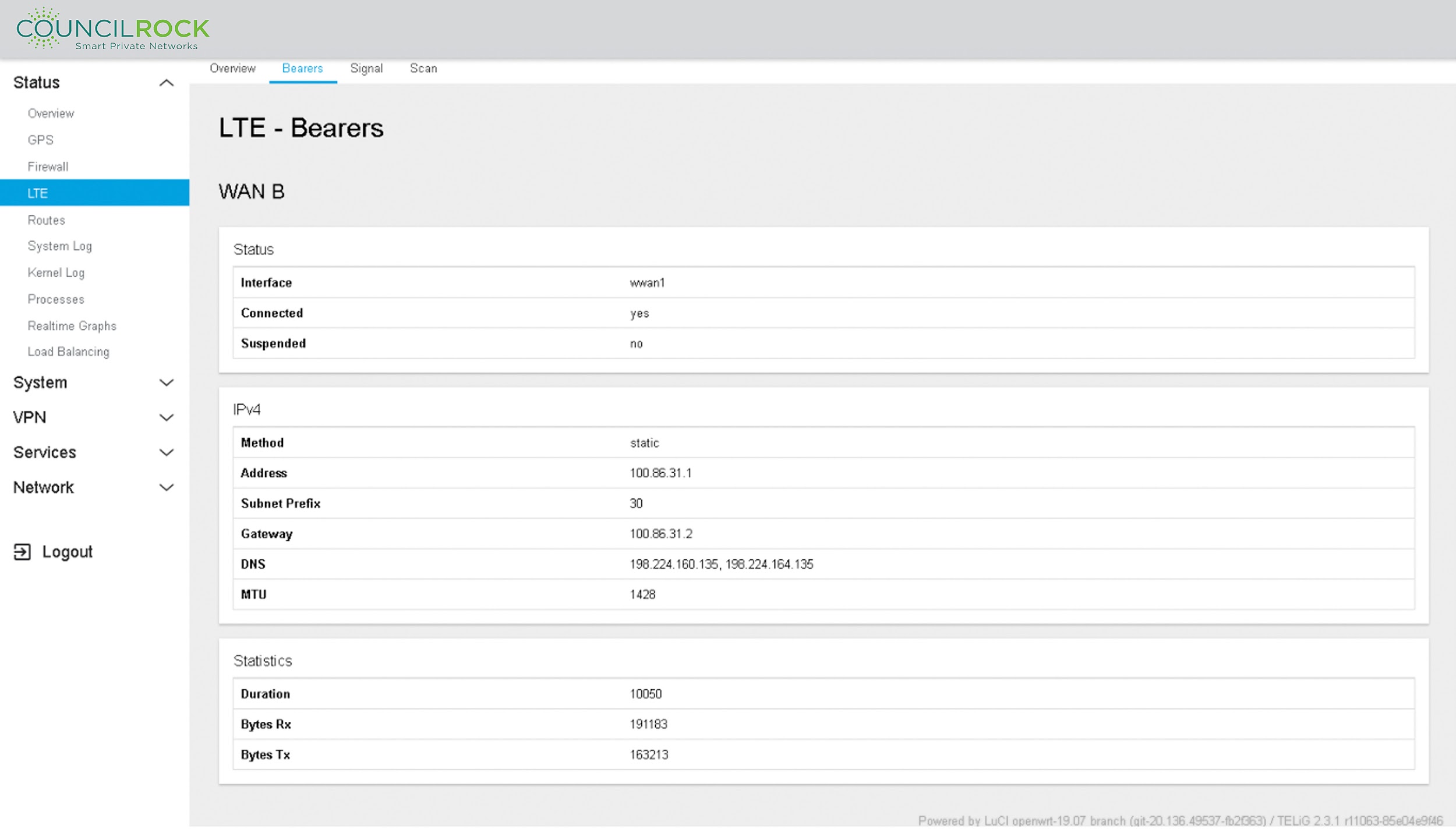 |
Interface: wwan0 (wireless WAN 0): the network interface created by the modem
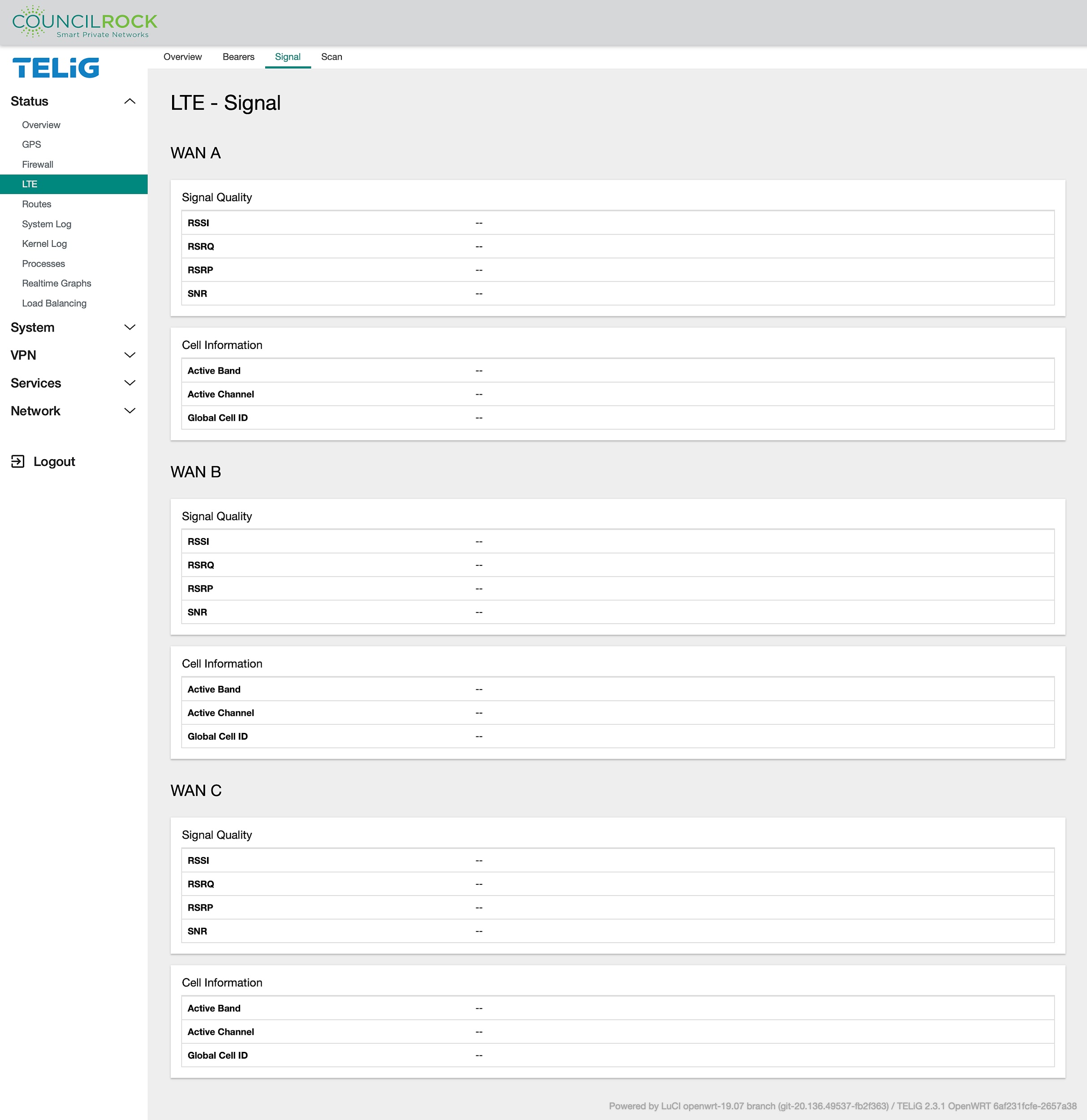
The Signal tab provides information for each modem present for the active band, channel, and cell, as well as quality information for the RF signal.
RSSI: Received Signal Strength Indicator. Provides measurement of power received by the radio modem in the frequency band, including noise.
RSRP: Reference Signal Received Power. Provides measurement of power of the LTE Reference signals spread over the full bandwidth and narrowband.
RSRQ: Reference Signal Received Quality. Provides measurement of the quality of the signal considering not only RSSI but also the number of used Resource Blocks
SNR: Signal to noise ratio. Provides measurement of the ratio of the power of the signal of interest to the average noise power within a specified bandwidth.
Signal quality level with respect to RSRQ thresholds (Referenced from TIA TSB-88.4 standards)
Signal Quality Level | RSRQ |
|---|---|
Excellent | ≥ -10 |
Good | -10 to -15 |
Fair | -15 to -20 |
Poor | < -20 |
 |
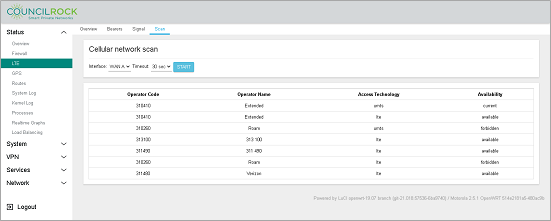
Finally, the Scan tab provides a tool for the user to perform a network scan for time intervals from 30 to 90 seconds using any system modems, listing carriers detected by modem. Details are given for Operator Code, Operator Name, Access Technology, and Availability.
 |
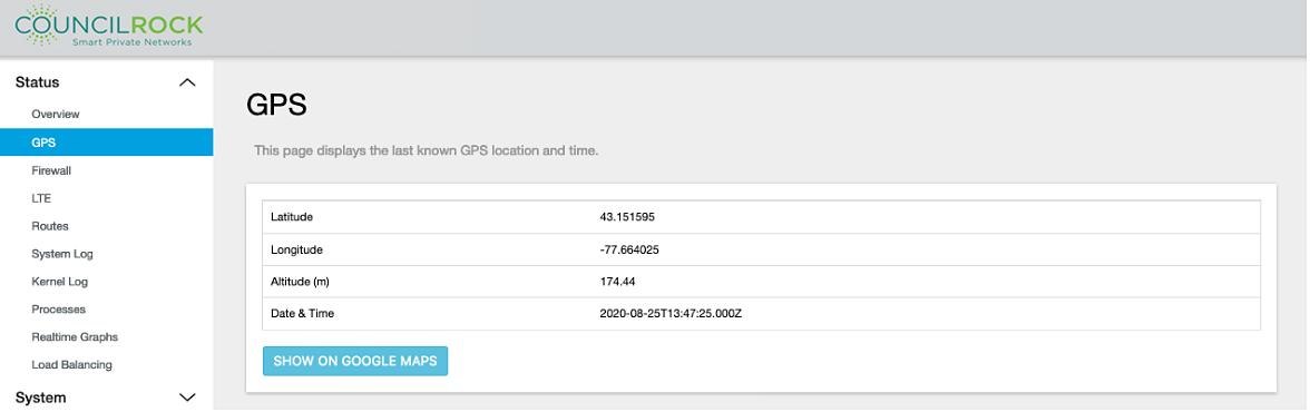
GPS
Information retrieved from the E1500's GPS connection is displayed. This includes the last known GPS location and time.
 |
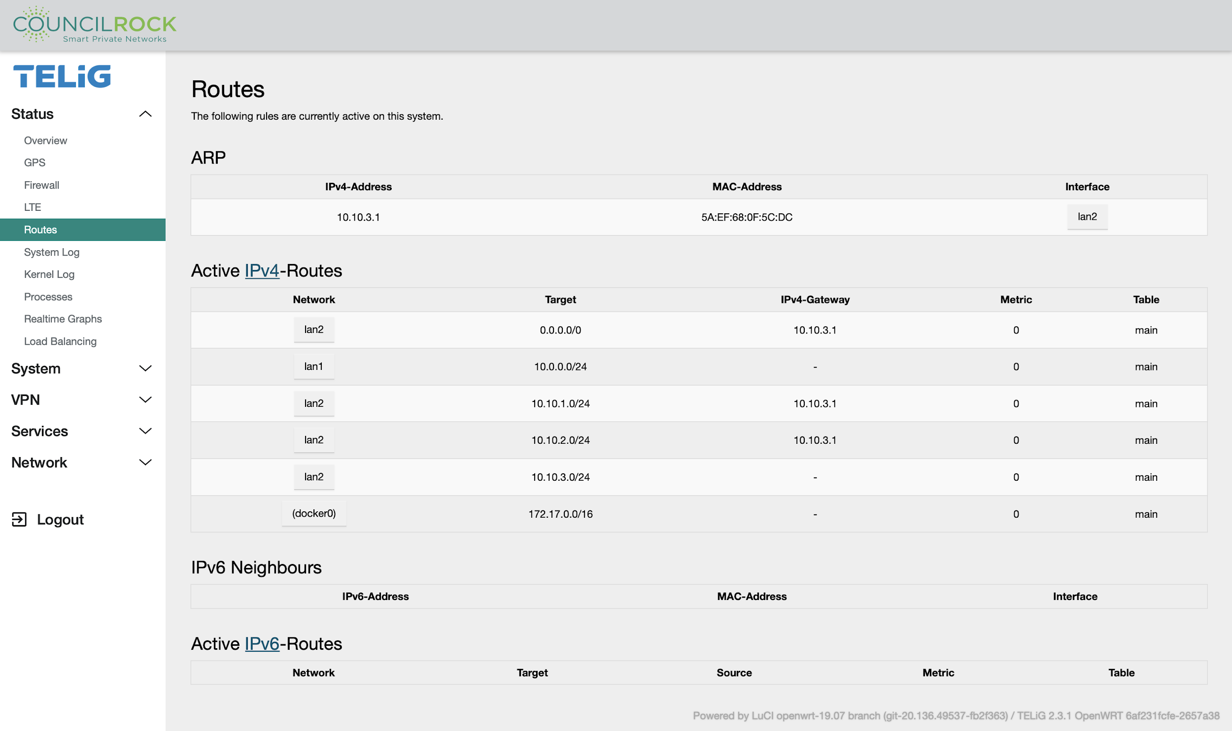
Routes
Displays information on currently configured routing rules. The rules are divided into IPv4 and IPv6. An ARP table and an IPv6 neighbors table are also provided.
 |
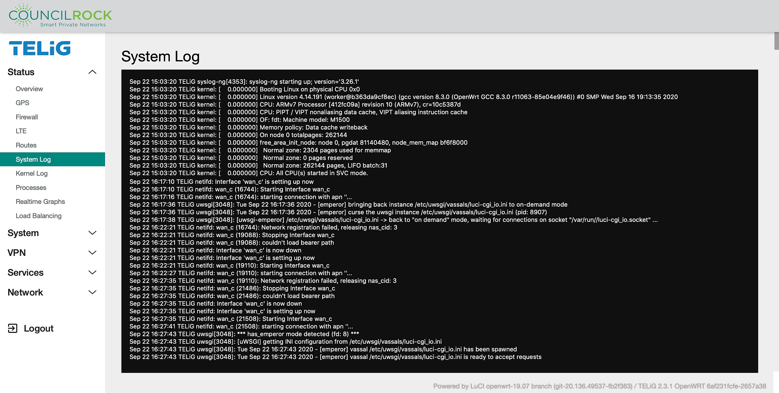
System Log
The operating system log output is displayed.
 |
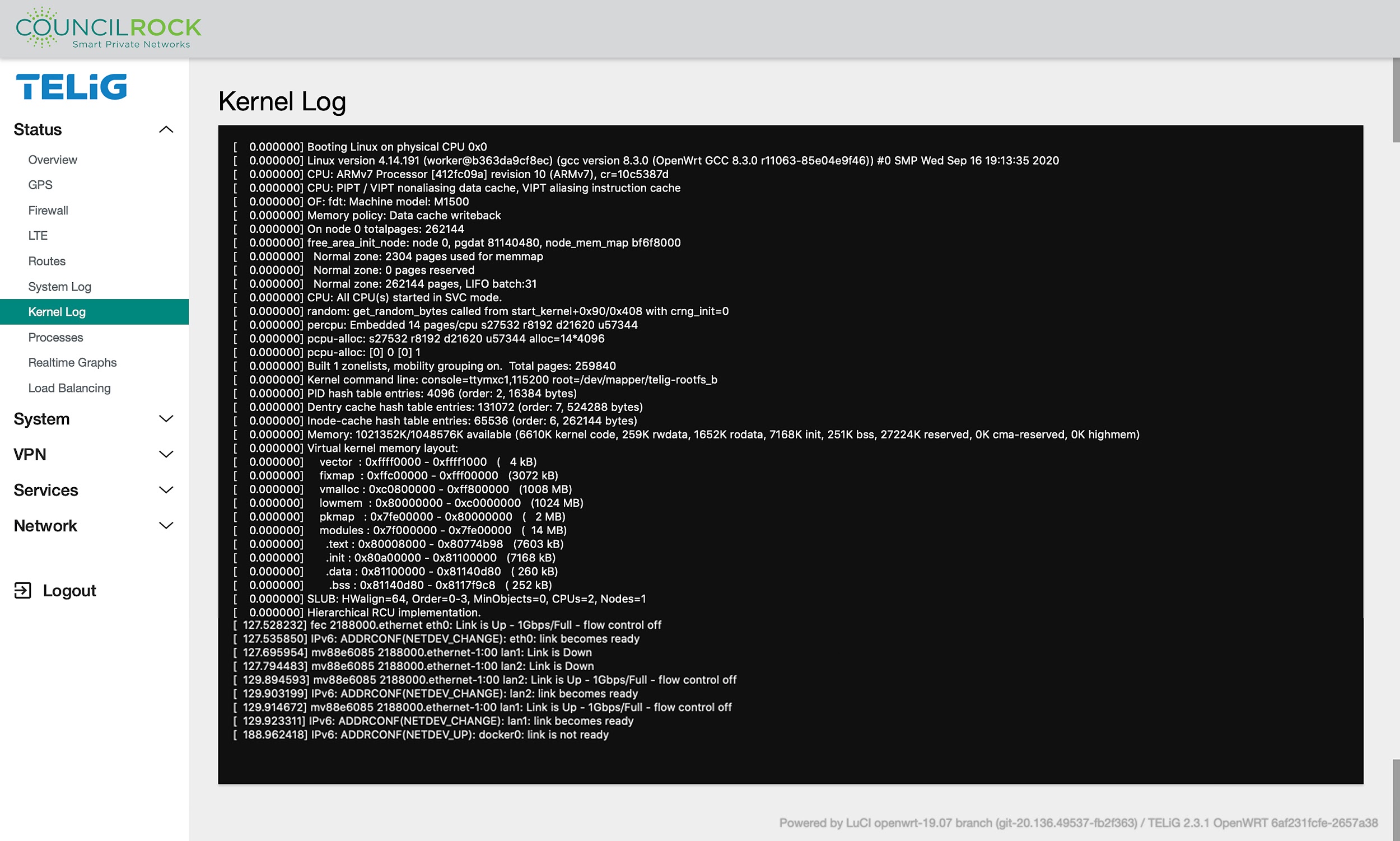
Kernel Log
The operating system kernel log is displayed.
 |
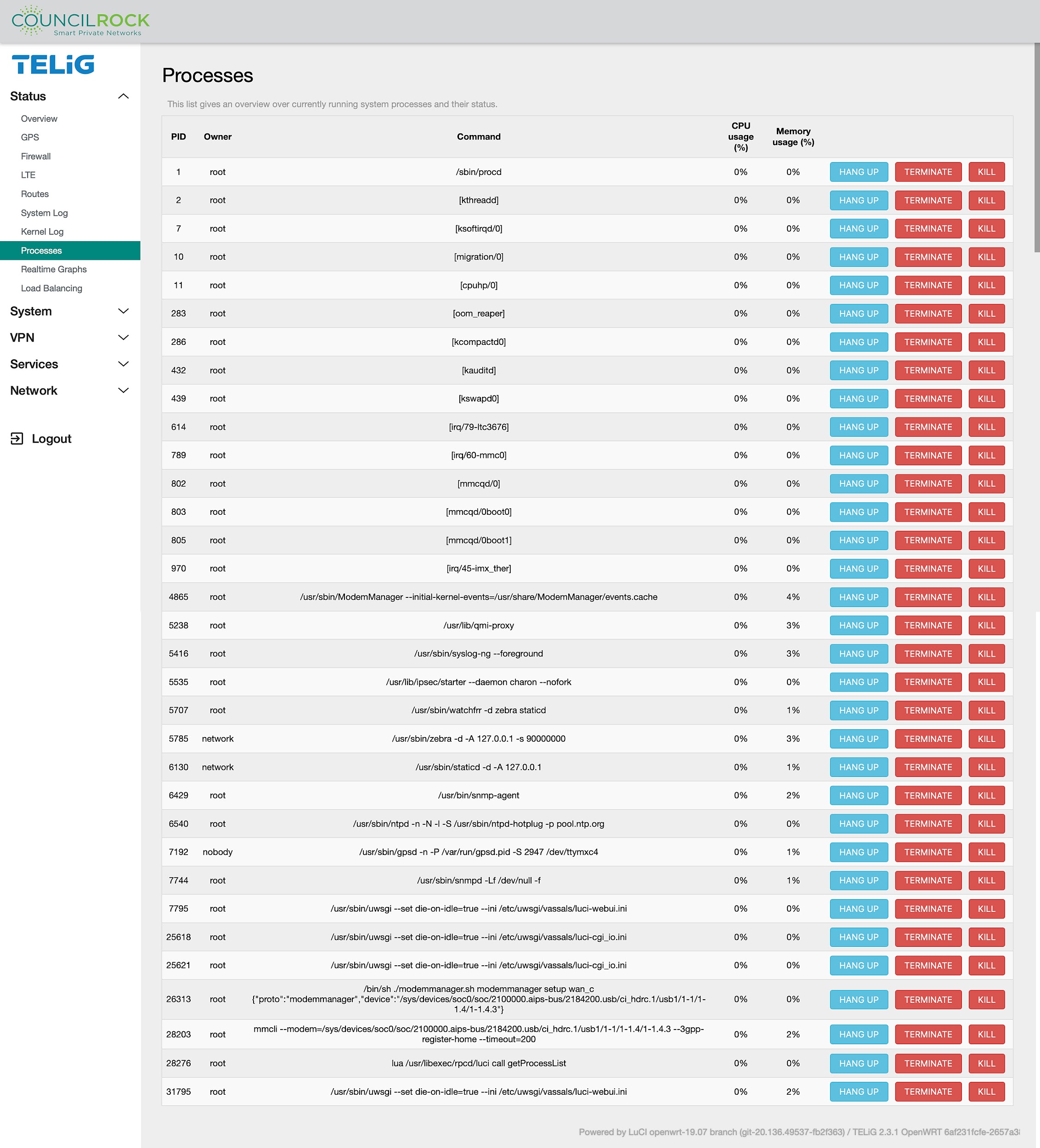
Processes
A list of currently running system processes is displayed, including process ID (PID), owner, command, and CPU / memory usage. To quit a process, action buttons are given for "Hang Up" and, to forcibly quit an unresponsive process, the more aggressive "Terminate" and "Kill".
 |
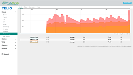
Realtime Graphs
Displays live graphs of system performance.
The Load tab displays a live graph of the queue of processes handled by the CPU, as well as average and peak loads for the past 1, 5, and 15 minutes. Note that in a single core CPU, a load of 1.0 is considered fully loaded.
 |
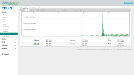
The Traffic tab shows a live graph of inbound and outbound traffic as well as a table of average and peak inbound and outbound traffic. At the top of the graph is a selectable list of interfaces.
 |
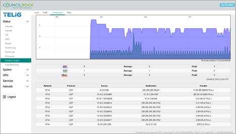
The Connections tab provides a live graph of network connections, divided into TCP, UDP, and others, including averages and peaks. A table lists each active connection, its protocol, source, destination, and amount of data transferred.
 |
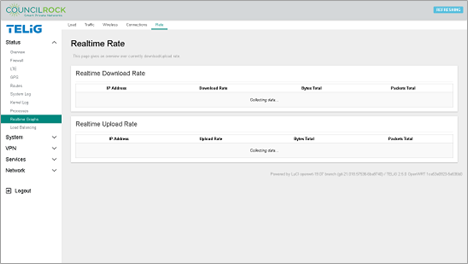
Finally, the Rate tab shows the real time download and upload rates by IP address, as well as total bytes and total packets over which the rate is calculated.
 |
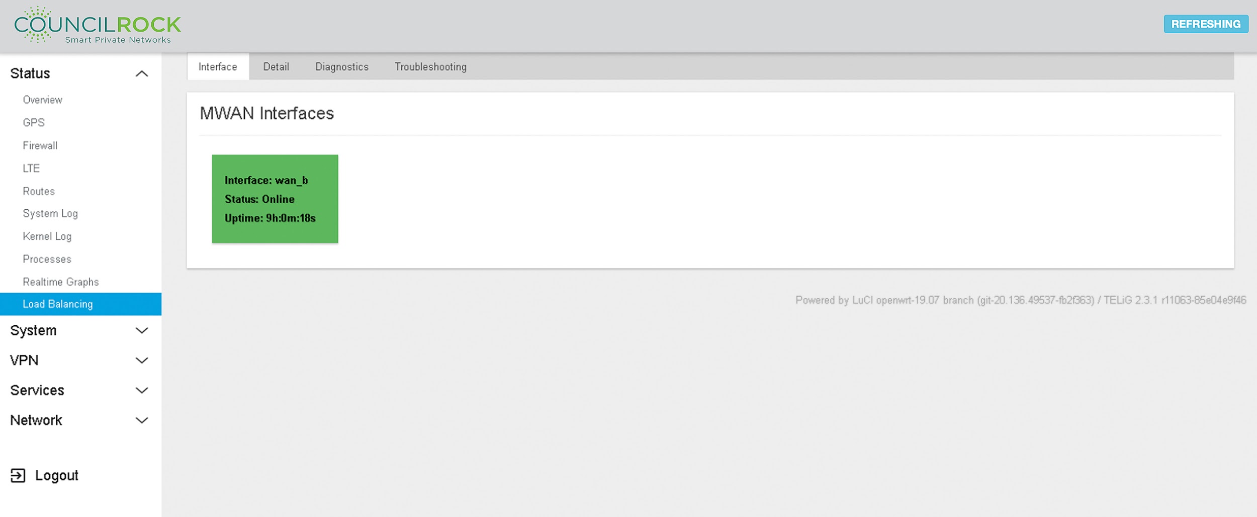
Load Balancing
Provides information on MWAN interfaces. The Interface tab lists all available MWAN interfaces and their status.
 |
MWAN interfaces are the interfaces participating in a configured load balancing process. See LAN to WAN Traffic or Radio Module Failover use cases for details on how to configure these interfaces.
The Detail tab provides information from the operating system on interface status, IPv4 and IPv6 policies, and connected IPv4 and IPv6 networks.
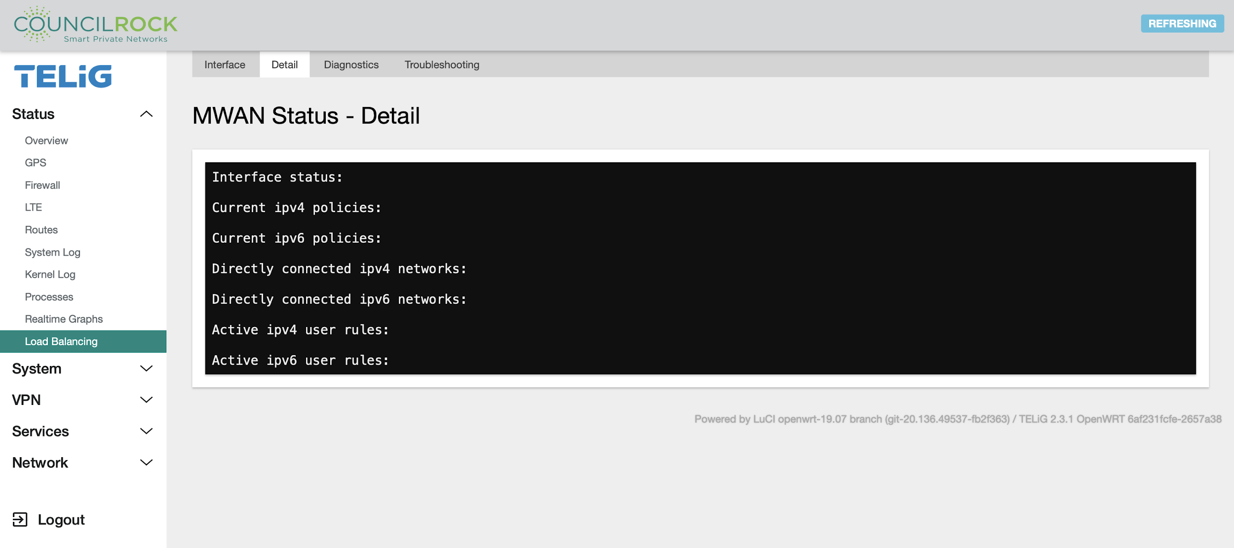 |
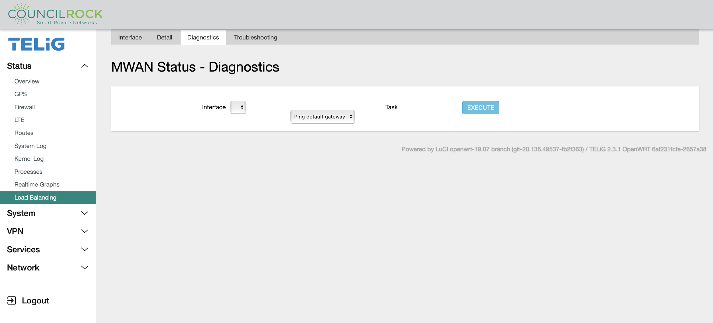
The Diagnostics tab includes basic tools for testing MWAN interfaces (Gateway ping, Ping tracking IP, Check IP rules, Check routing table, Hotplug ifup, Hotplug ifdown).
Gateway Ping: Pings the interface gateway IP address defined for the WAN interface associated with the MWAN interface
Ping tracking IP: Pings the “Tracking hostname or IP address” defined on Network > Load Balancing > Interfaces
Check IP rules: Displays which routing table the MWAN interface will use to route traffic
Check routing table: Displays the routing table defined for the WAN interface associated with the MWAN interface
Hotplug ifup: Enables the specified MWAN interface
Hotplug ifdown: Disables the specified MWAN interface
 |
The Troubleshooting tab shows the operating system’s output after running diagnostic commands. Information on network interfaces, active routes, routing, and firewall rules can be inspected on the output display.
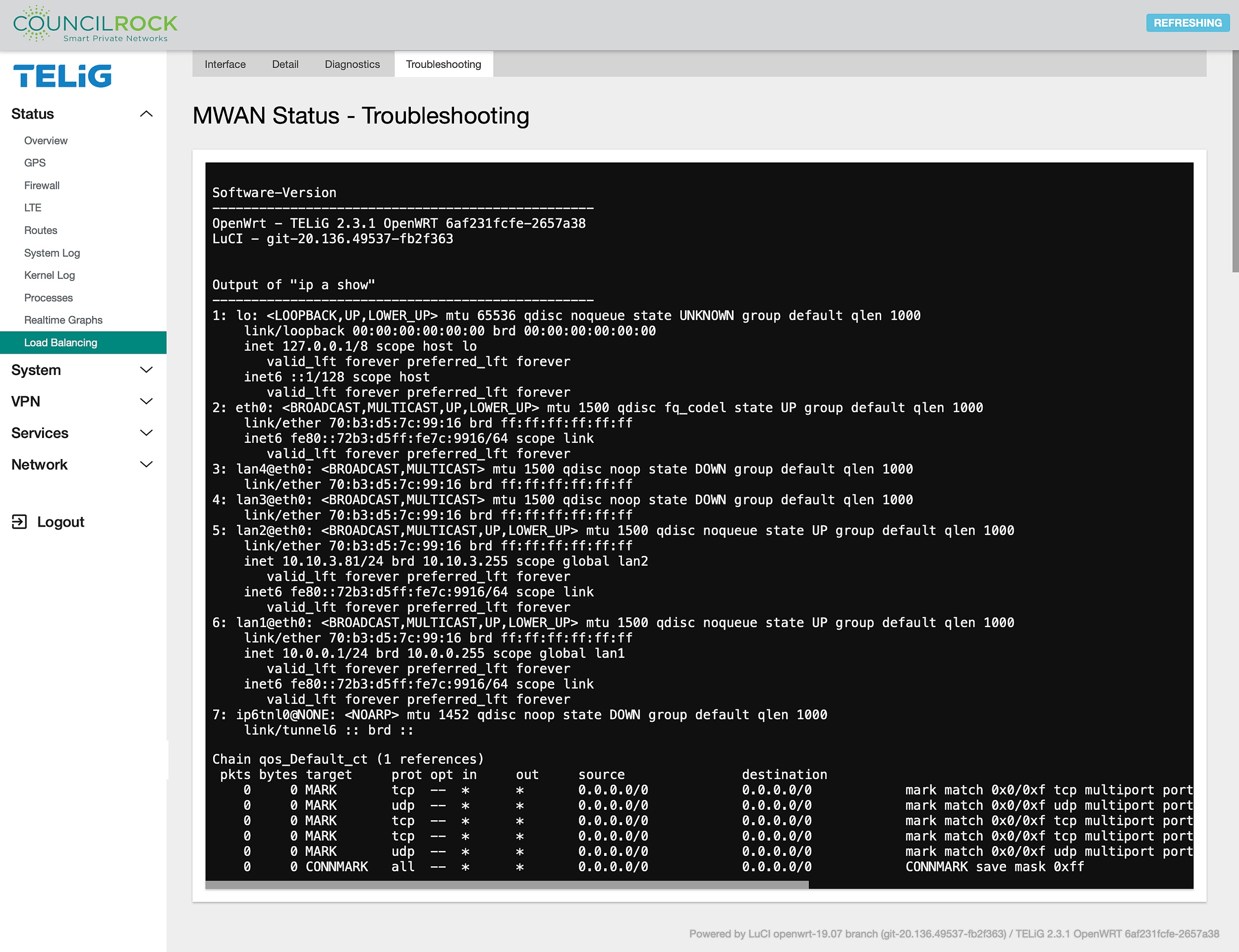 |
SYSTEM
System menus provide access to the unit’s settings. Here the user can rename the unit and set the administrator password and time settings. Firmware backups/updates are handled here as well as installation and removal of software packages, system startup tasks and recurring tasks. Serial port protocols can be set. Advanced users can configure and execute custom commands (shell commands) defined by an admin user. Finally, the user can perform a soft reboot on the unit from the System menus.
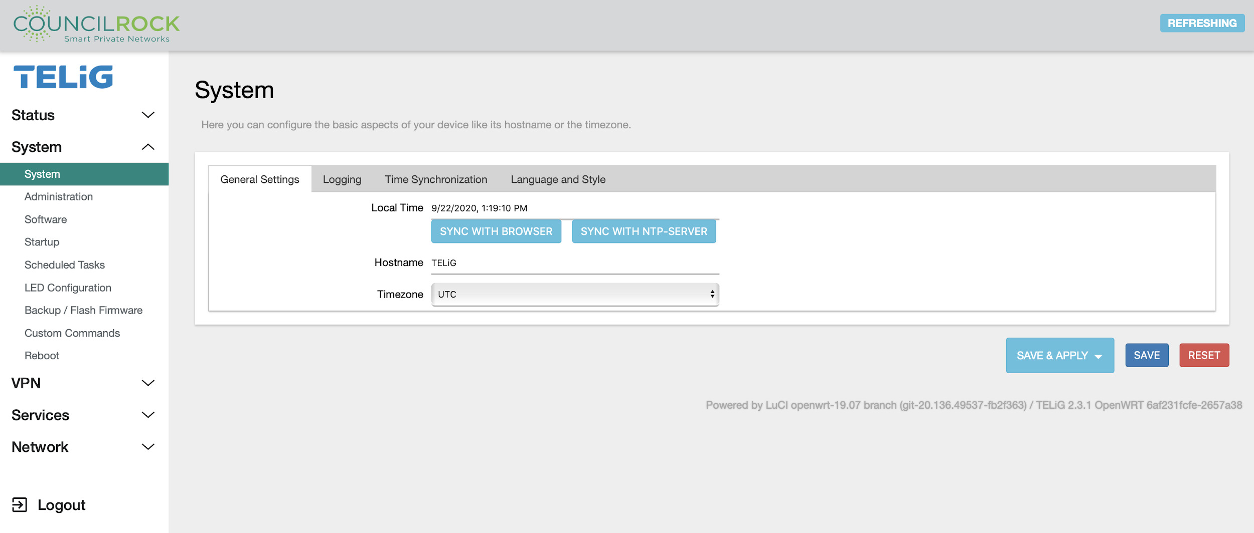
System Submenu
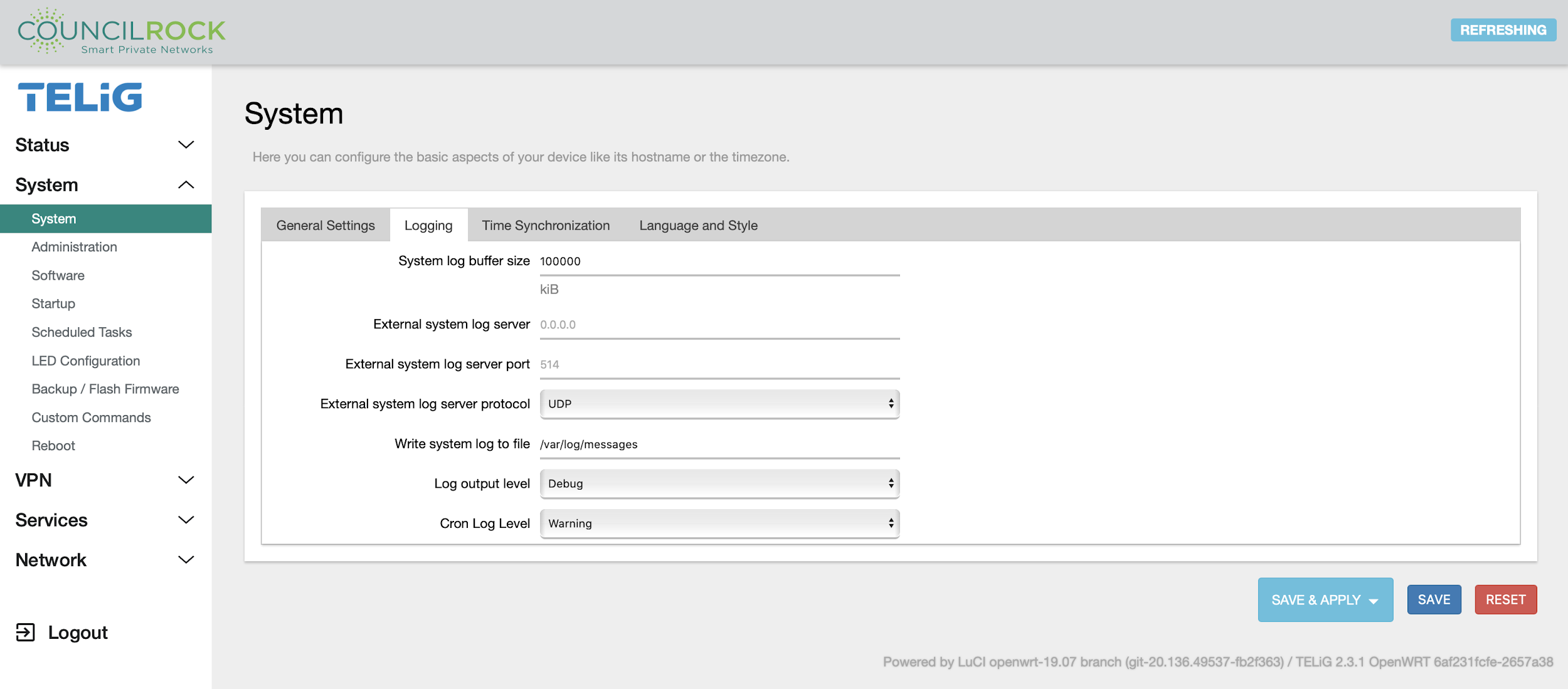
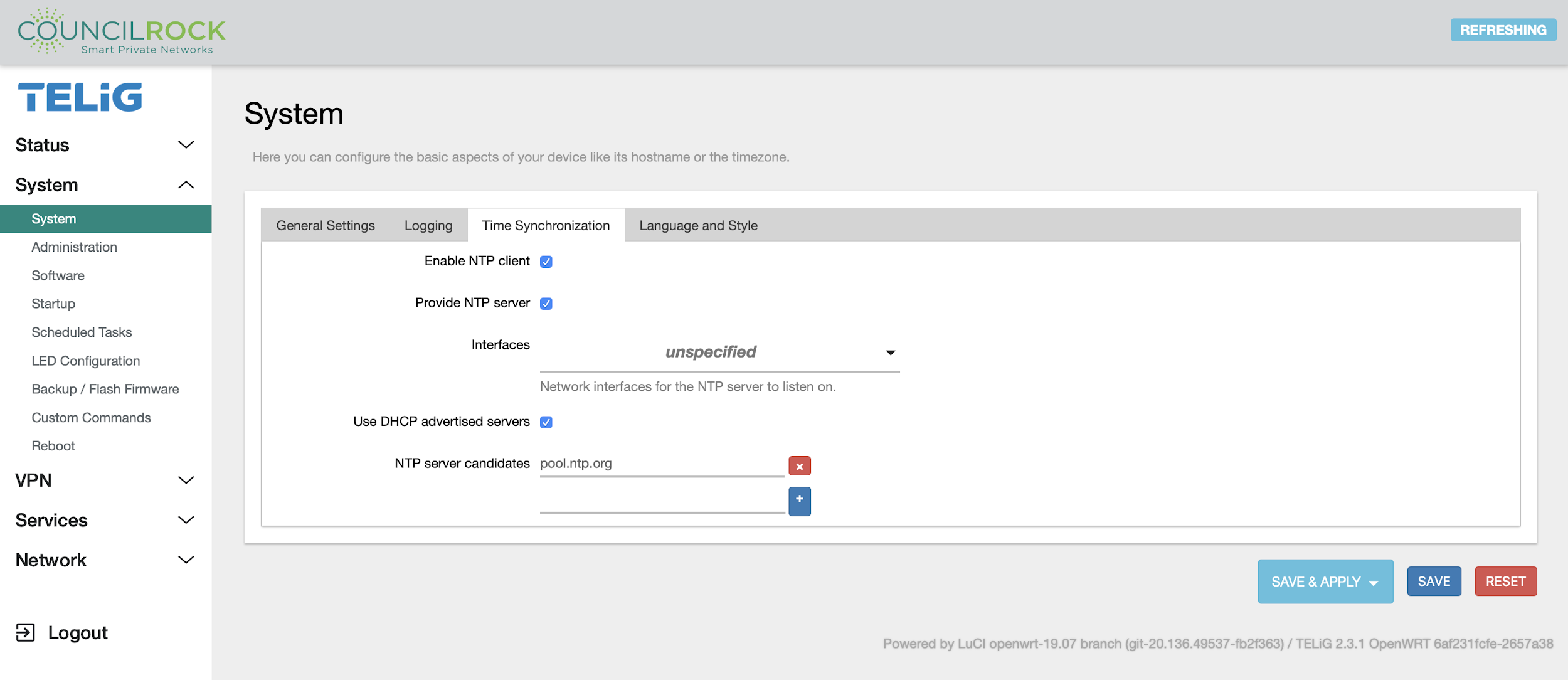
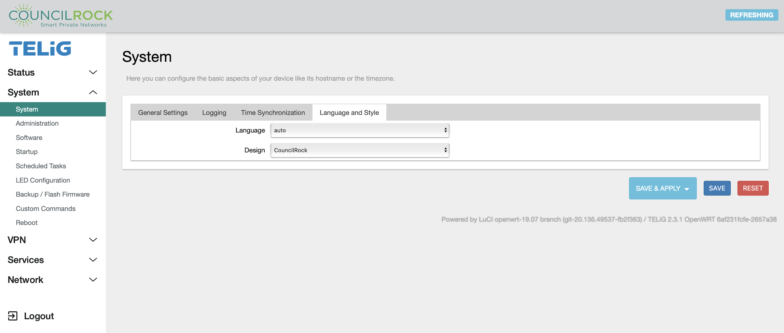
The System submenu provides access to overall unit settings. The General Settings tab lets the user set time, hostname, and time zone. The Logging tab has settings for the log buffer size, log output level, and log file save location. The Language and Style tab lets the user set the GUI theme and language.
 |
 |
 |
 |
Administration
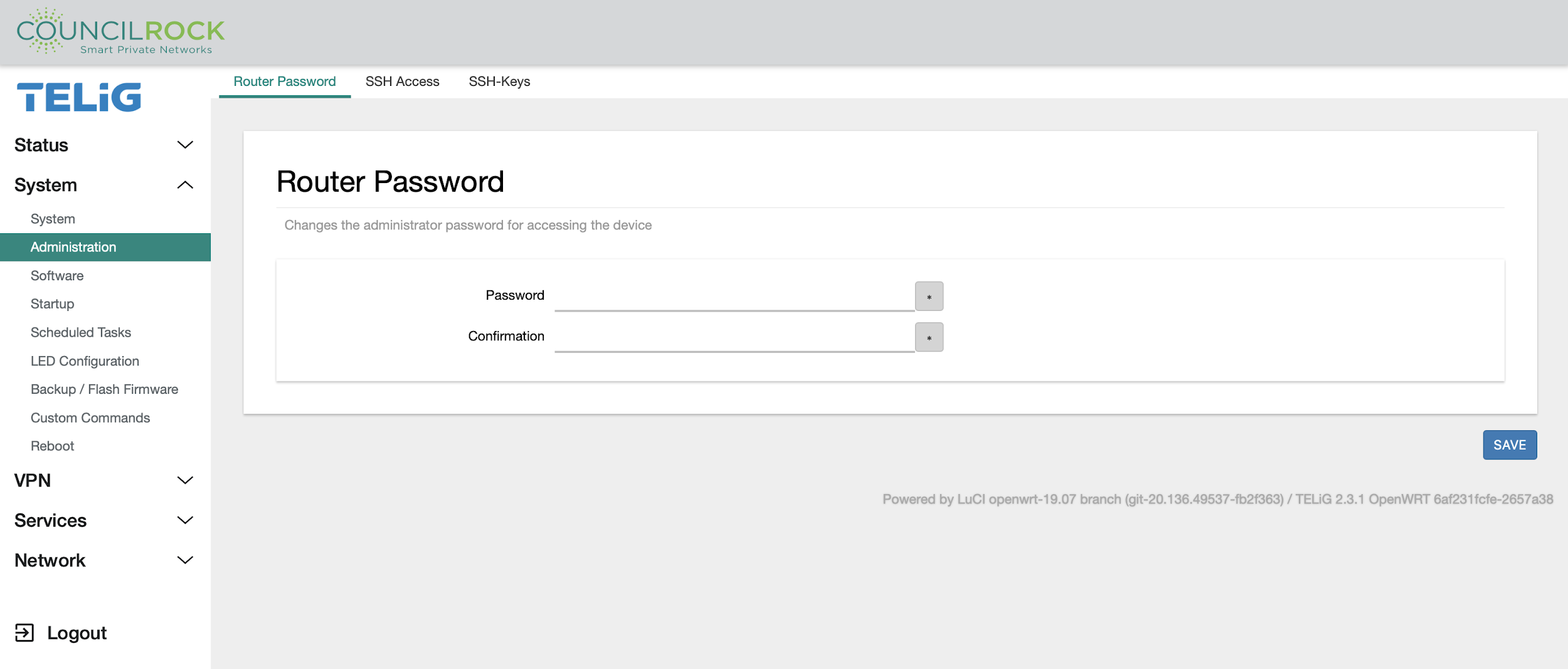
Usernames and passwords are configured in the Administration submenu.
The Router Password tab lets the user change the device’s root password. The root user is currently the only user who can access the GUI. Future firmware revisions will allow other users to access the GUI.
 |
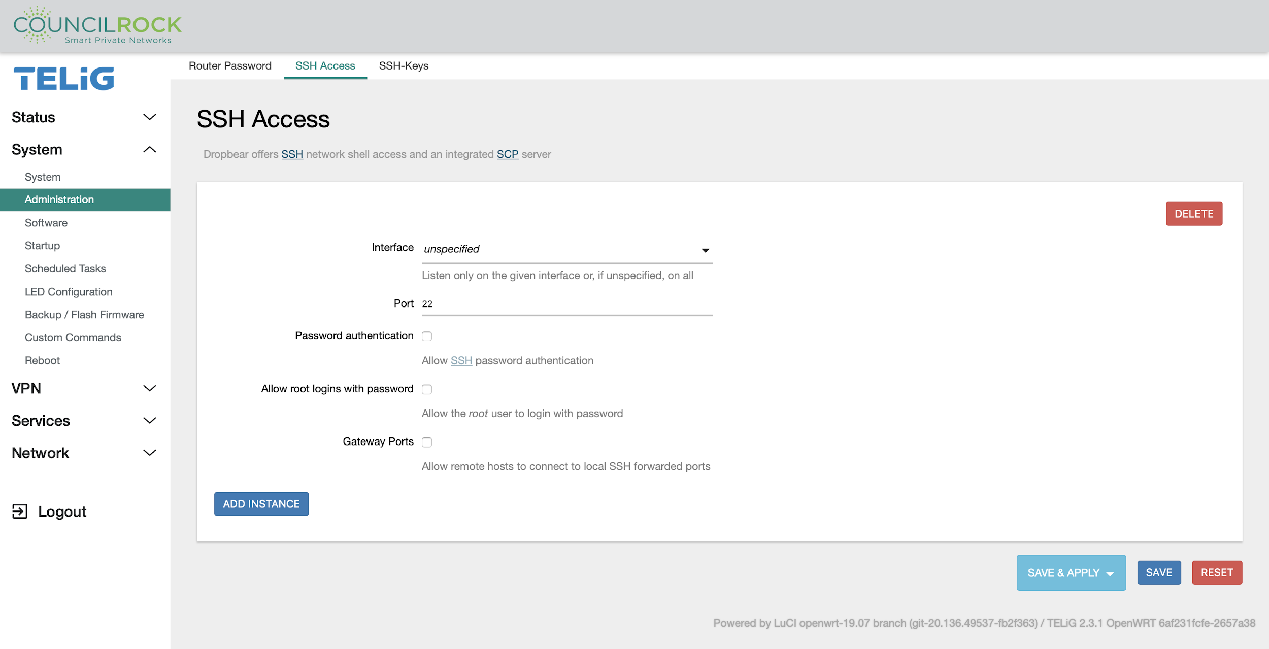
The SSH Access tab lets the user enable or disable general users and/or the root user over SSH with password authentication. SSH can also be restricted via access to a specified interface & port.
When the “Password authentication” box is checked, all users except ‘root’ will have password authenticated access to the unit via SSH.
When the “Allow root login with password’ box is checked, only the ‘root’ user will have password authenticated access via SSH.
 |
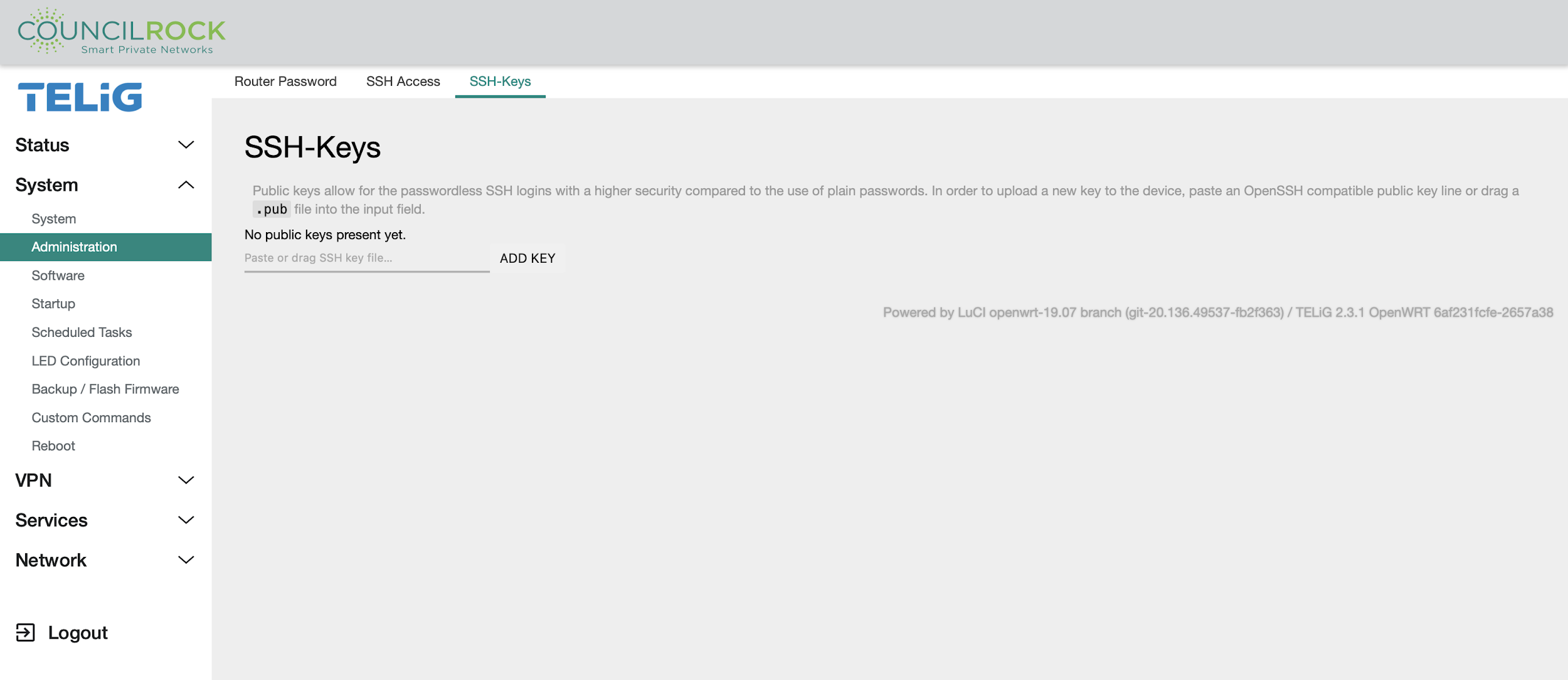
The SSH-Keys tab displays uploaded SSH public keys, and lets you upload an SSH public key to access SSH using public-private keypair authentication.
 |
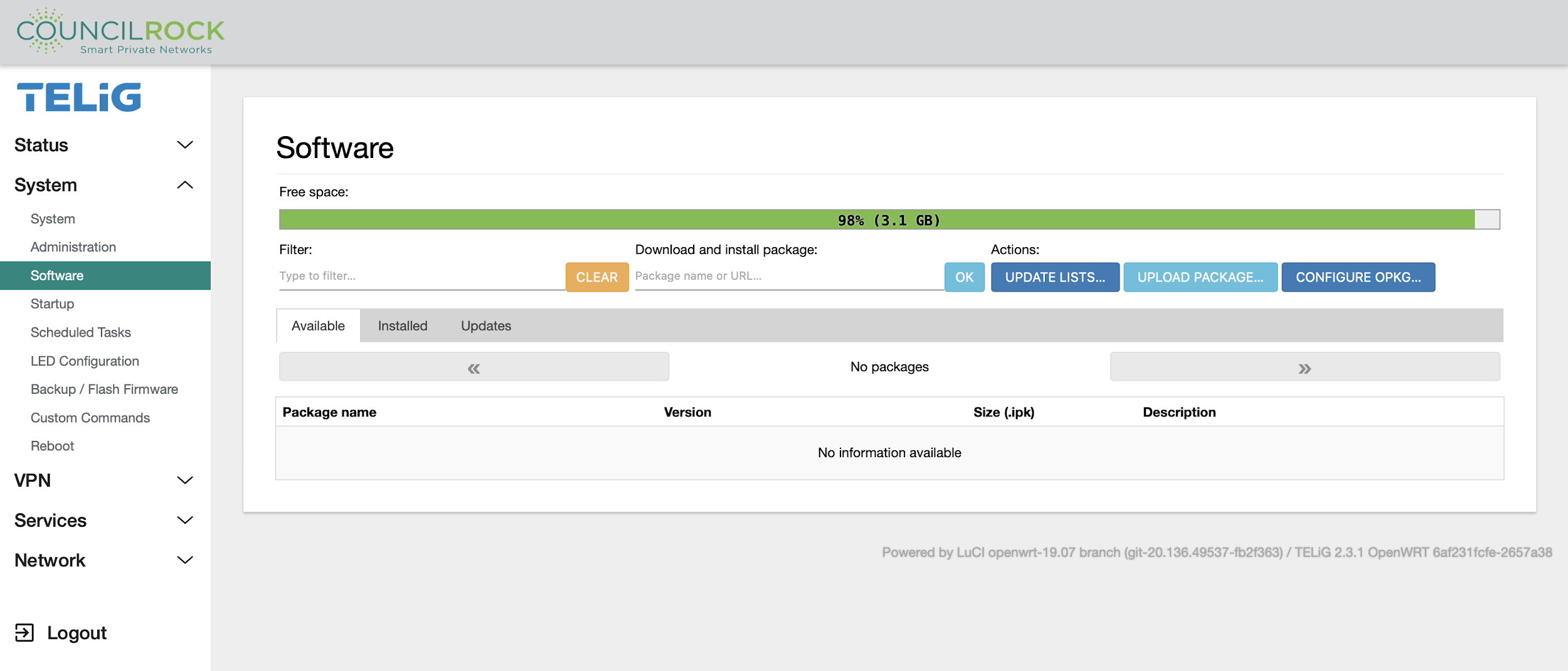
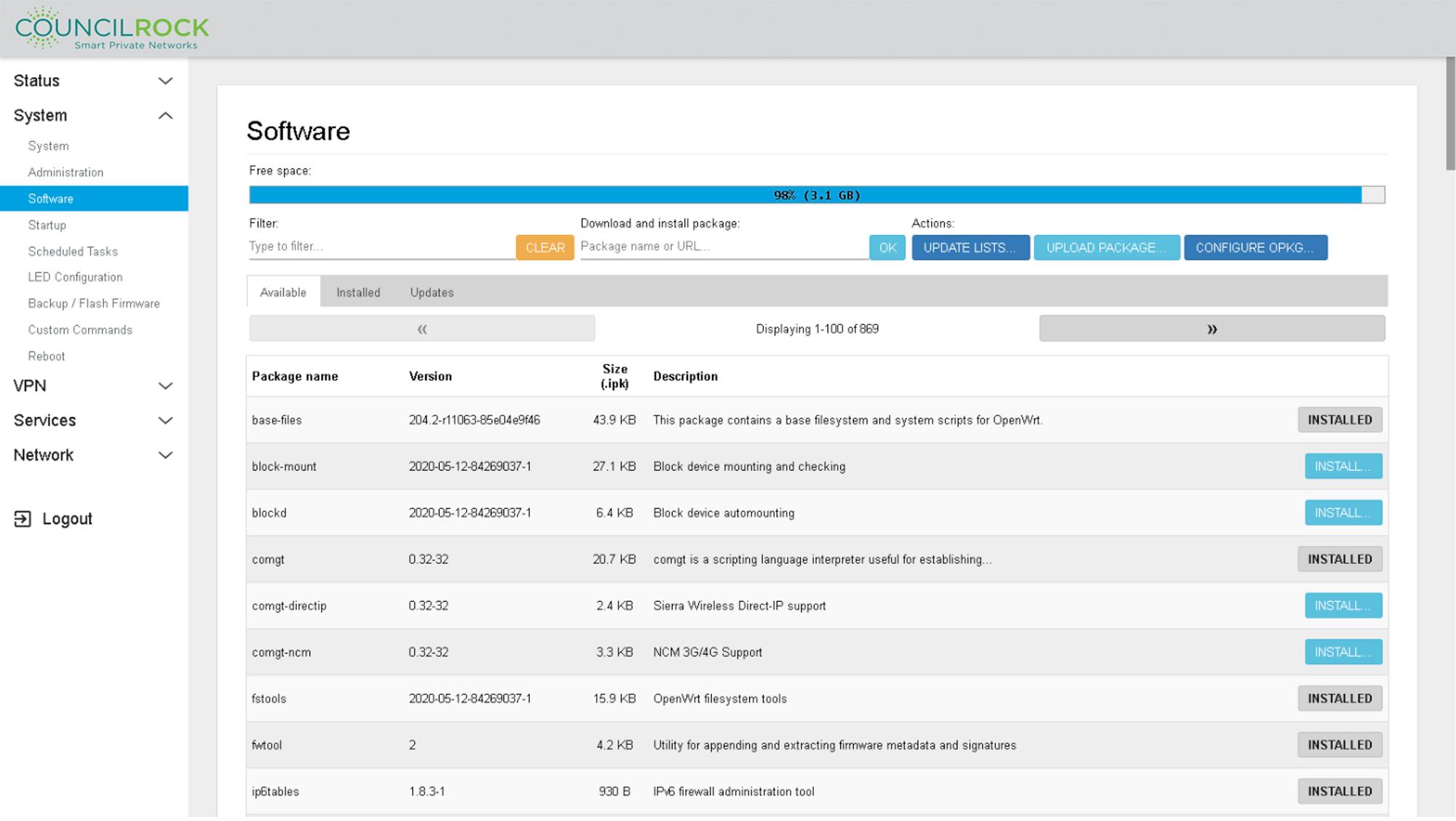
Software
The Software menu displays free space on the device, and allows the installation, removal, and updating of software packages. The Available tab shows packages available through the configured package manager. The Installed tab shows currently installed packages and allows for their removal. The Updates tab shows installed packages with available updates and lets the user update to the latest version.
Important
Installing new packages is intended only for Advanced Users.
 |
To configure OPKG, click on the “Configure OPKG” option. The following screen will pop up.
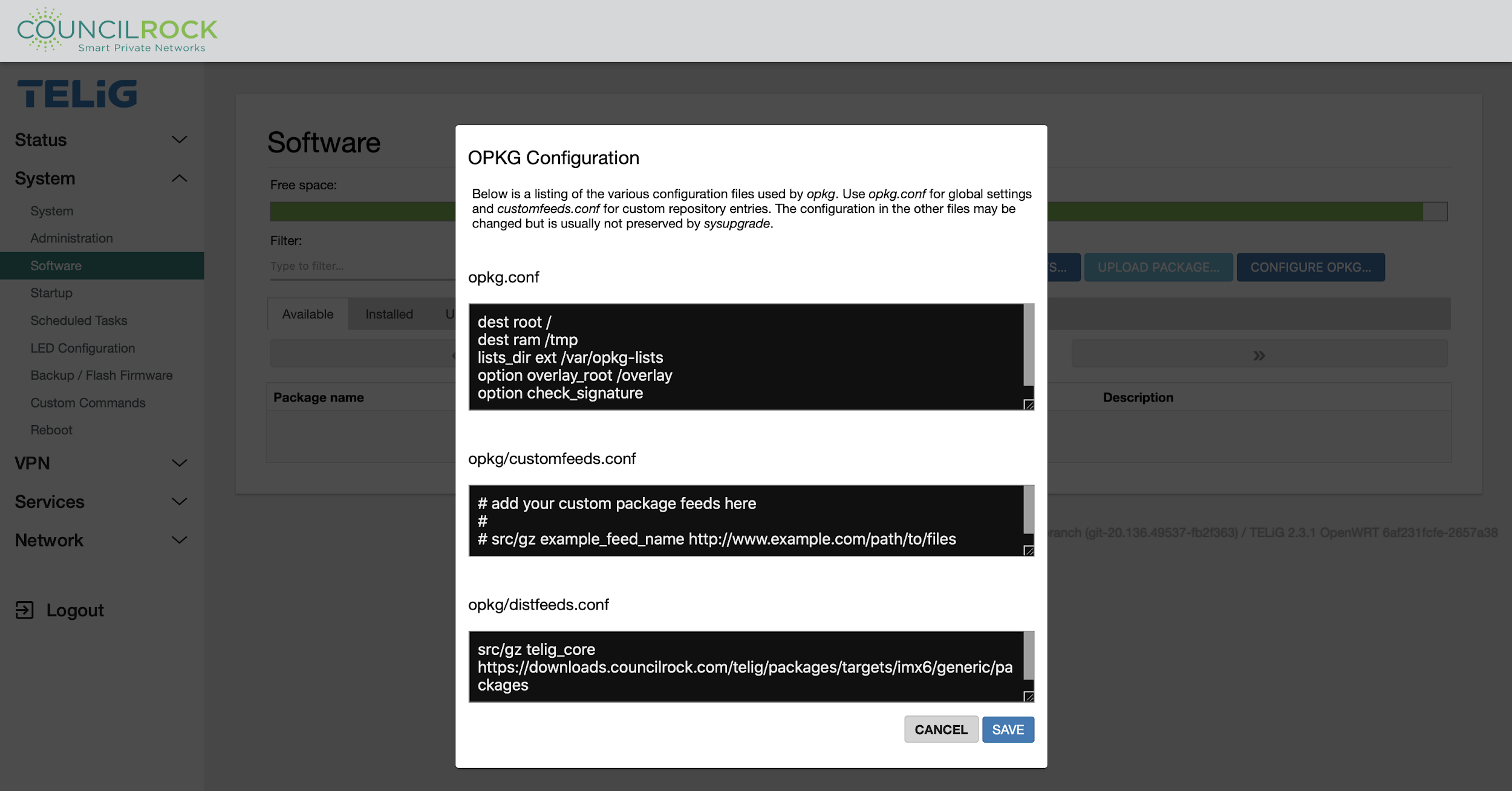
On the OPKG configuration screen, go to the last section “opkg/disfeed.conf” and change the default repository to the desired repository where you are hosting the packages you would like to install. Click SAVE after you are done.
Click the UPDATE LISTS button to show the available packages in the newly configured repository. After that point you can install new packages from the list by clicking the INSTALL... button and then clicking on INSTALL in the pop up window.
Important
UPDATE LISTS triggers the unit to connect to a remote server to query availability of software packages. The unit must be configured with network visibility to this server prior to performing this action.
 |
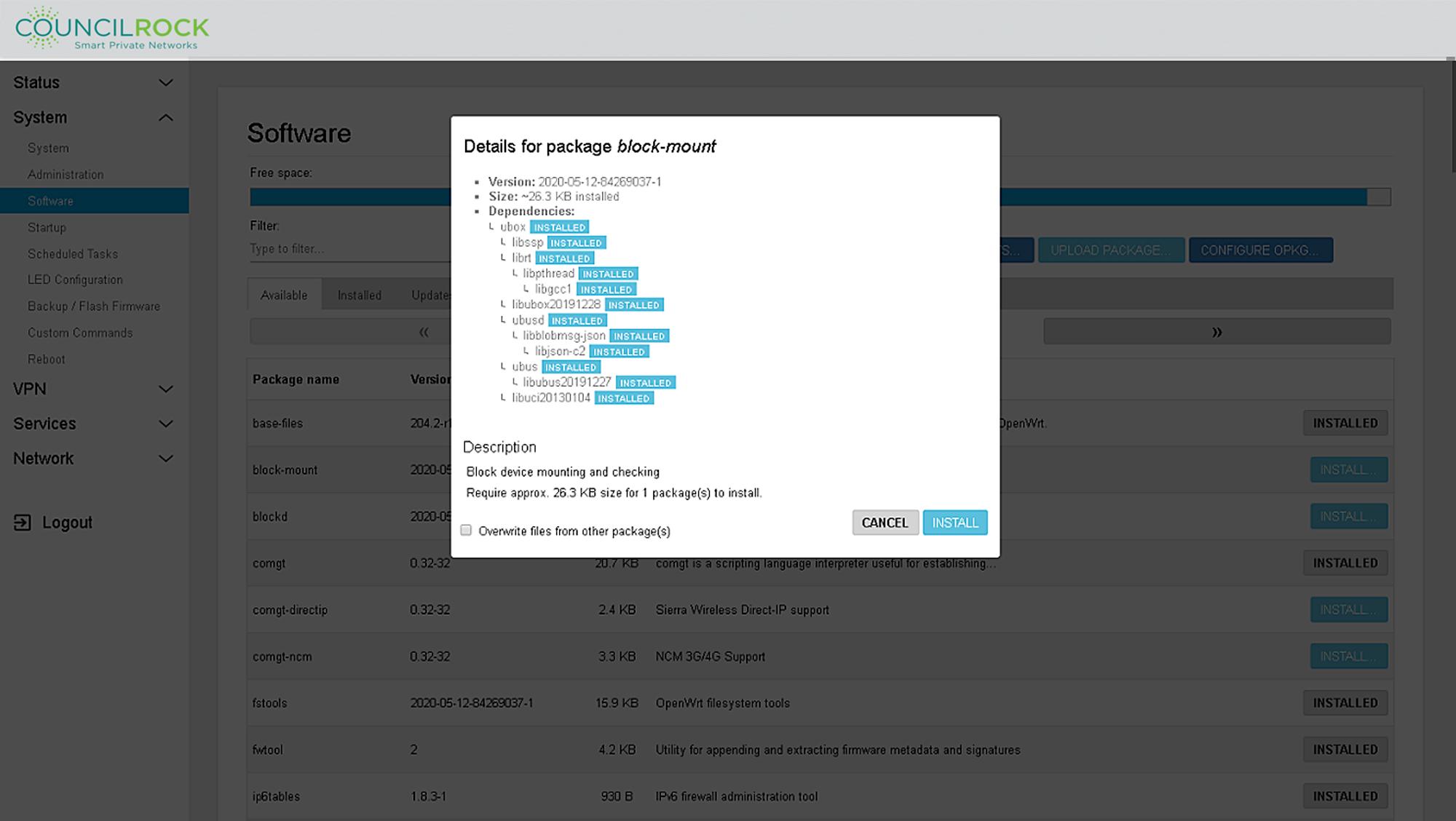 |
Clicking ‘INSTALL’ will show software details as in the example ‘block-mount’ package shown above. Software details including Version, Size, and Dependencies are displayed. A description of the software package is shown at the bottom. The option to overwrite files from other package(s) is selectable with a check box. From this dialog, the user can select CANCEL to go back or INSTALL to install the software package.
Startup
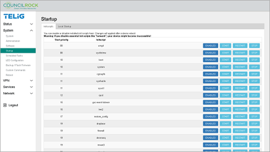
The Startup submenu lets the user configure startup and initialization programs.
The Initscripts tab displays a list of available initialization scripts, their priorities, and whether they are enabled or disabled (for run on startup). You can also toggle scripts between enabled and disabled, and manually start, restart, or stop a script.
 |
The Local Startup tab lets the user enter a custom shell script, to be executed after the enabled system initialization scripts listed on the Initscripts tab.
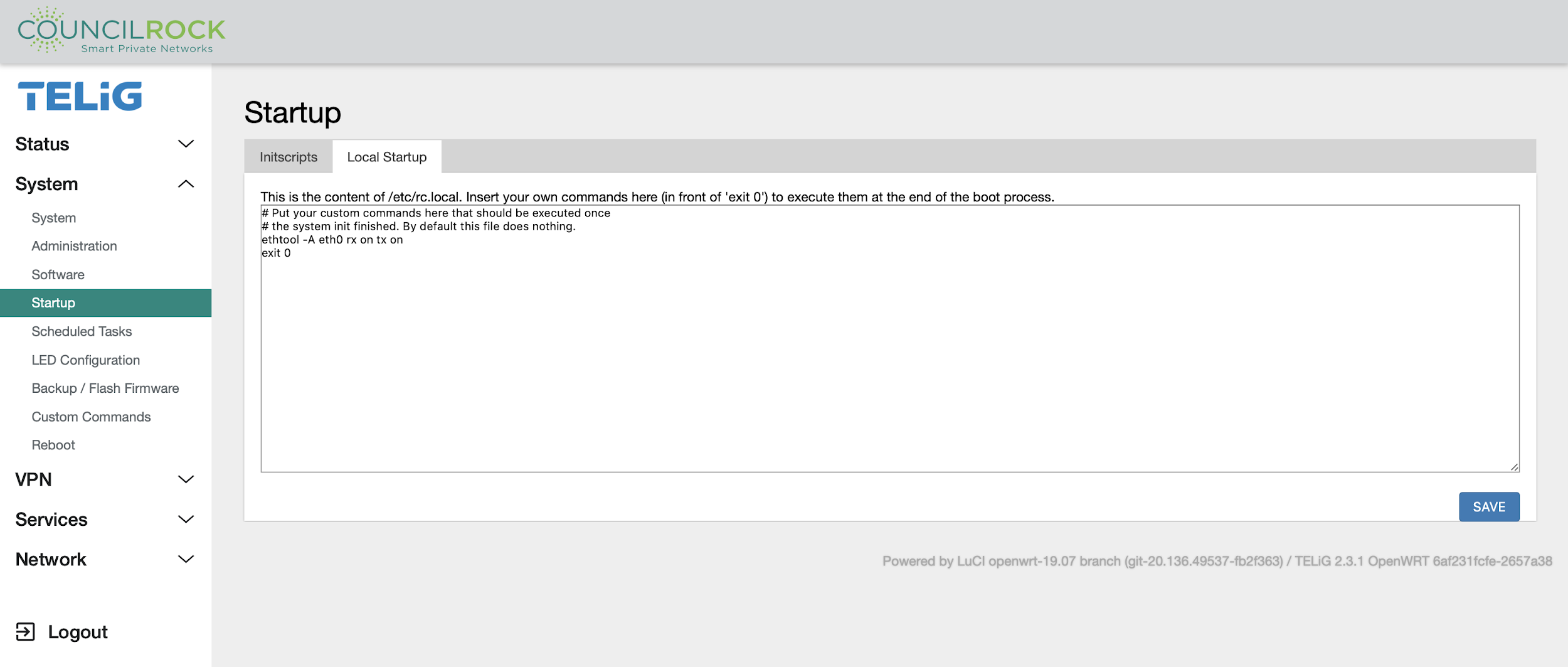 |
Important
Custom Shell Scripting is intended only for Advanced Users.
Scheduled Tasks
Here the user can set up “cron jobs” - recurring tasks which are configured to run on a set schedule.
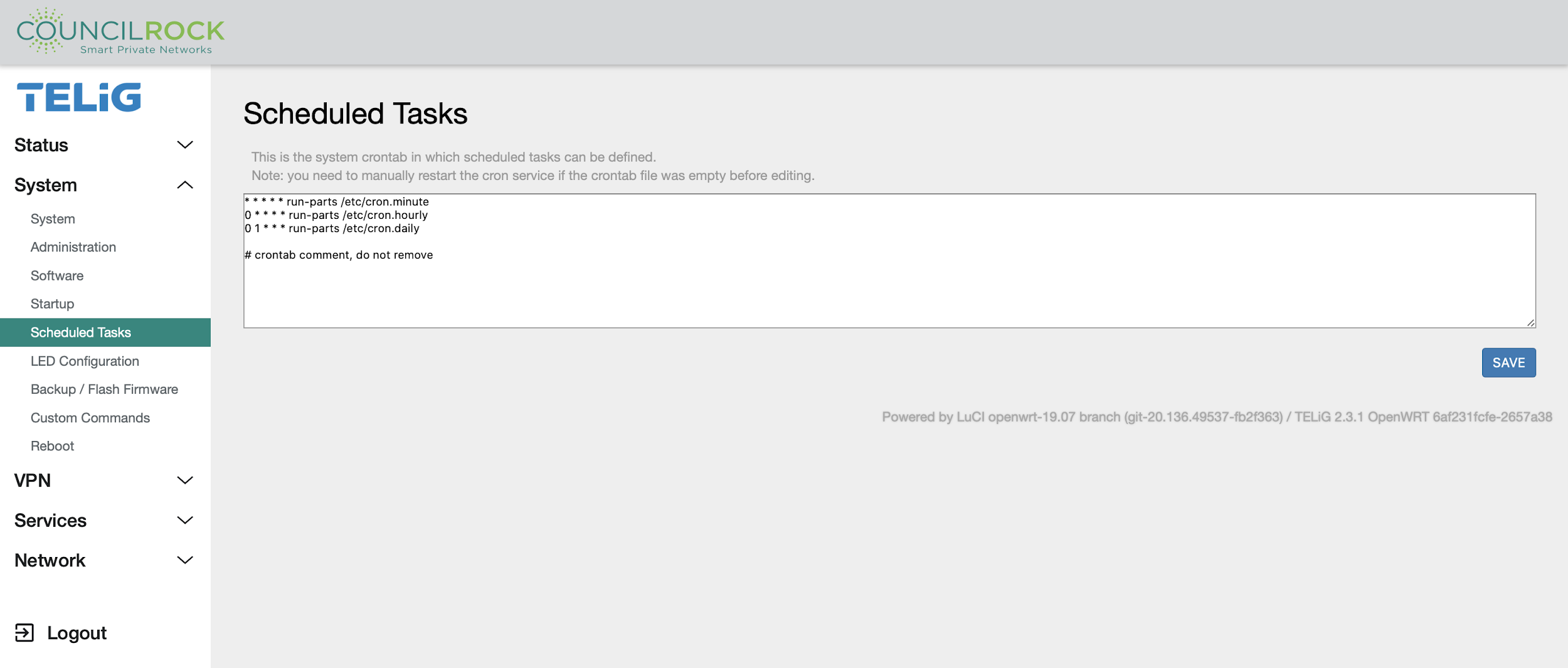 |
Important
Cron Jobs are intended only for Advanced Users
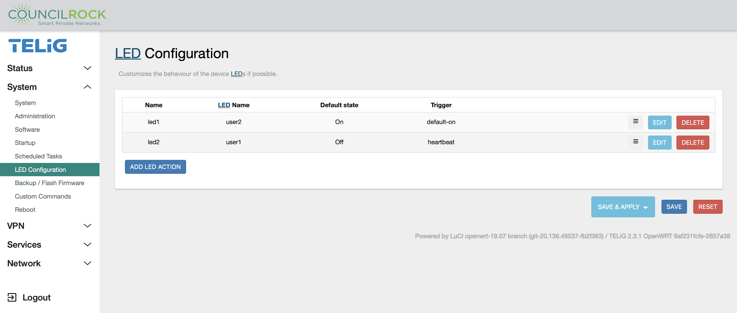
LED Configuration
The status LED is a red/green LED that can be customized to the user’s preferences.
The LED Configuration screen lists LED behaviors (actions) and lets the user edit, delete, and reorder them.
Important
LED configurations are overridden by LTE status indicators. If the E1500 unit has an active LTE interface, the LED actions shown on this screen will not apply. For details on LTE status indicators, see Front Panel
Since the status LED contains a green and a red LED, each color can be configured to its own action. For maximum clarity, a simple green ‘always on’ power indicator is typical. Multiple actions can be configured but for simplicity we recommend no more than a one-to-one mapping of a color to an action and amaximum of two actions in the list).
A new LED action can be added by clicking “Add LED Action “. To edit an existing action, click “EDIT.” Whether adding a new action or editing an existing action, the input fields are the same:
Name: Label the action. For clarity, we suggest the format "LED Color - action name"
LED Name: select "user1" for Green, "user2" for Red.
Default State: check = on, no check = off
Trigger: selected from the dropdown list
LED triggers are selected from the following options:
defaulton - Always ON
Heartbeat - Flash to simulate a heartbeat
mmc0 - ON when SD card is accessed
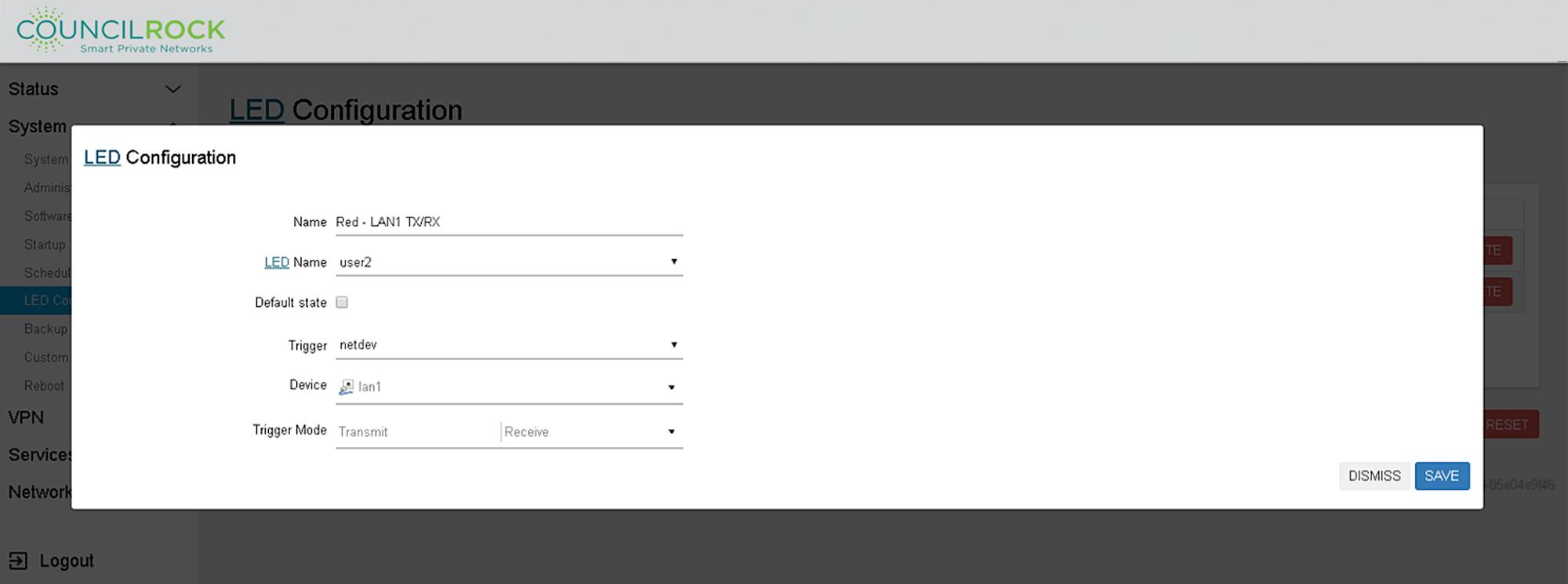
netdev - Flash with link status / send & receive activity - requires additional selections for device (from a dropdown list) and Trigger Mode (Link / Transmit / Receive - multiple selections allowed)
none - Always OFF
timer - Blinks at a specified rate. Specify On-State Delay and Off-State Delay in milliseconds. For example, to turn the LED on for one second and blink off for half a second, On-State Delay = 1000 and Off-State Delay = 500
usbdev / usbport - ON when a specified USB device or port is connected. Select a USB device or port from the dropdown list.
 |
The example configuration shown above is set up for a green ‘always on’ power indicator with a simultaneous red LAN1 send/receive indicator. Note that the red LED in this example will act the same as the existing ethernet port LED - and therefore is not a recommended LED action based on the rule of thumb of simplicity.
“Netdev” trigger settings for the red LED action are seen below.
 |
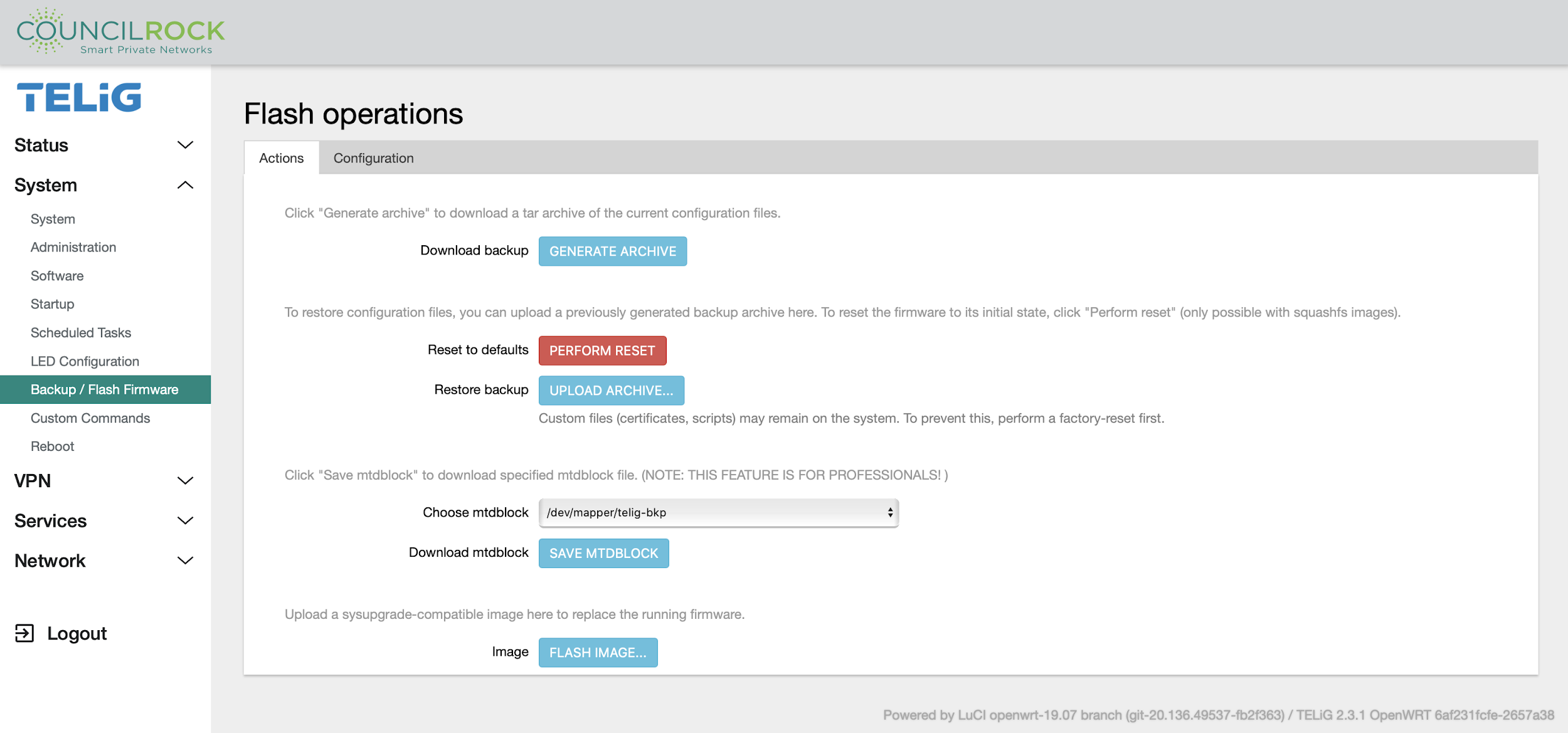
Backup / Flash Firmware
This menu gives access to the unit firmware.
The Action tab lets the user backup and restore firmware.
GENERATE ARCHIVE: download a backup archive to your computer
PERFORM RESET: reset the unit back to default settings (factory reset)
UPLOAD ARCHIVE: upload a backup saved on your computer to the unit
Choose mtdblock / SAVE MTDBLOCK: select an mtdblock and download it as a file
FLASH IMAGE: manually flash a firmware update
 |
Warning
mtdblocks are a Linux method of interacting with Flash memory via a simple Flash Transition Layer (FTL) within a Linux Memory Technology Device (MTD) subsystem. use of mtdblocks is recommended only for advanced users familiar with this Linux concept.
The Configuration tab gives the user the option to specify files and directories to be preserved when flashing new firmware.
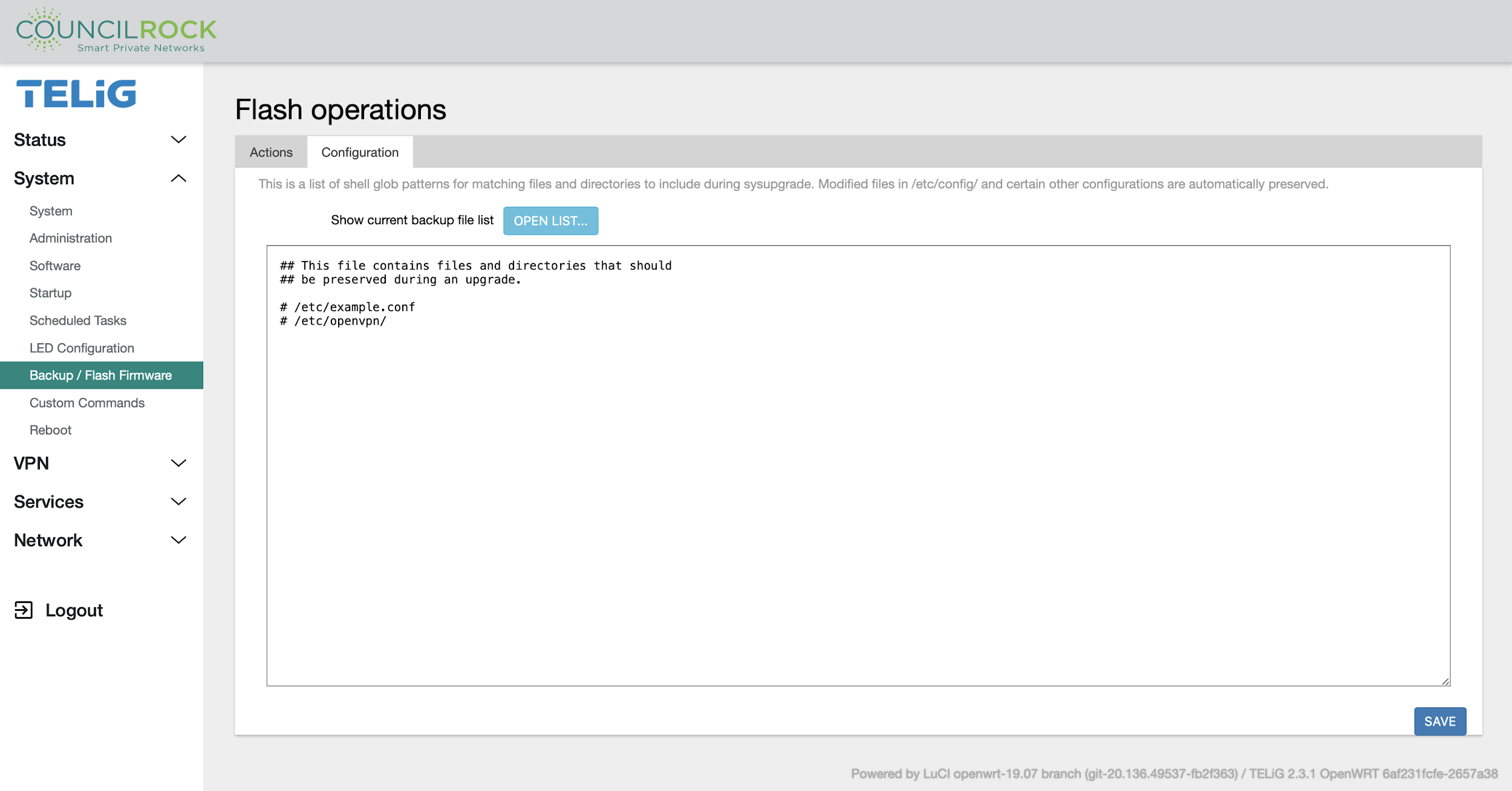 |
Custom Commands
Allows for setup and execution of custom commands. These can be any applicable Linux command typically run from a command line interface. As such, these commands should only be performed by an advanced user.
The Dashboard tab displays currently configured custom commands and provides a button to run the command. Clicking RUN will display the command output at the bottom of the page when the command has completed.
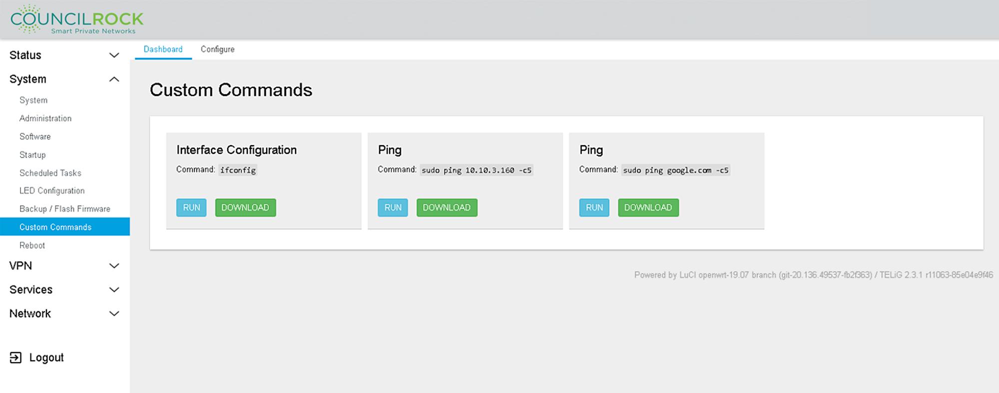 |
Note
Commands shown are provided as examples. A new unit will not have custom commands set up.
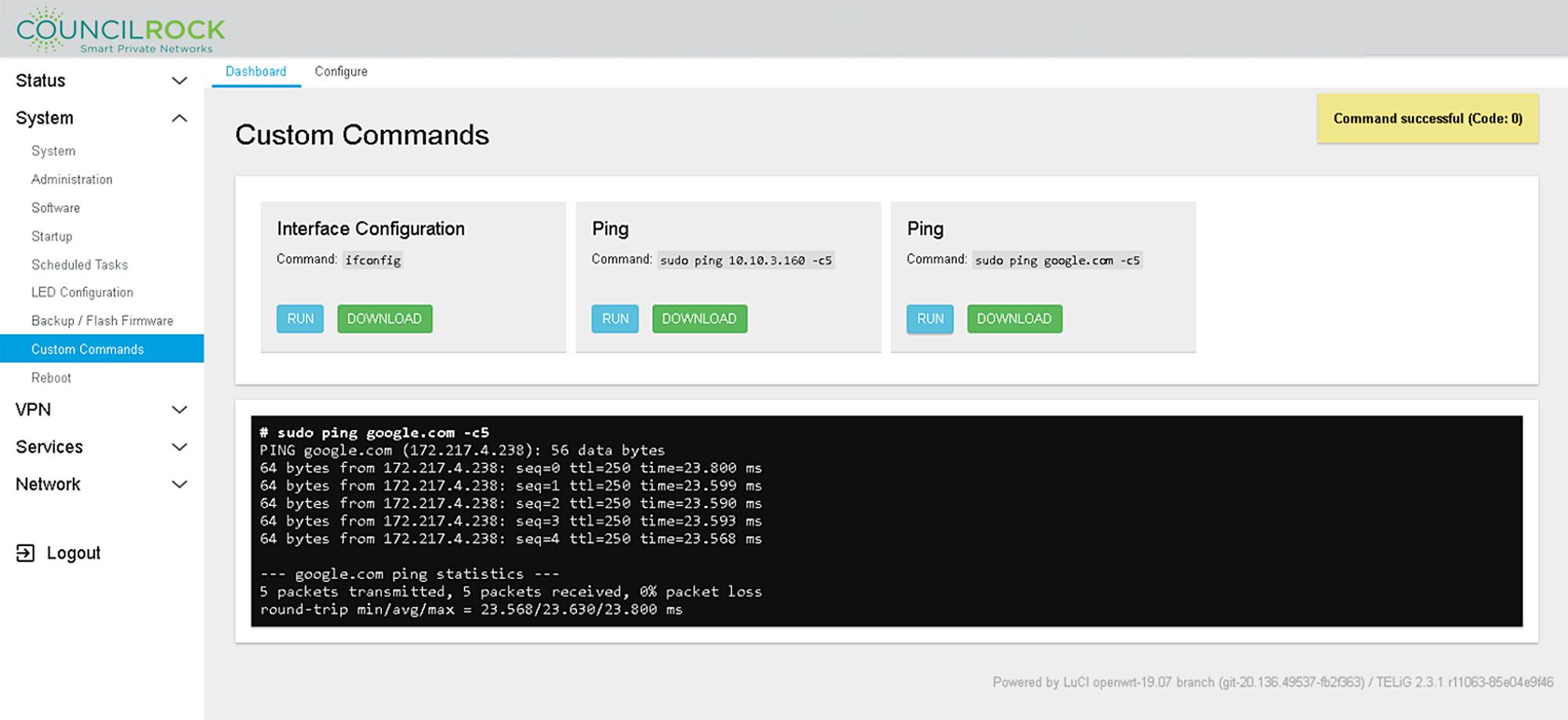 |
Showing results of 'sudo ping google.com -c5' command
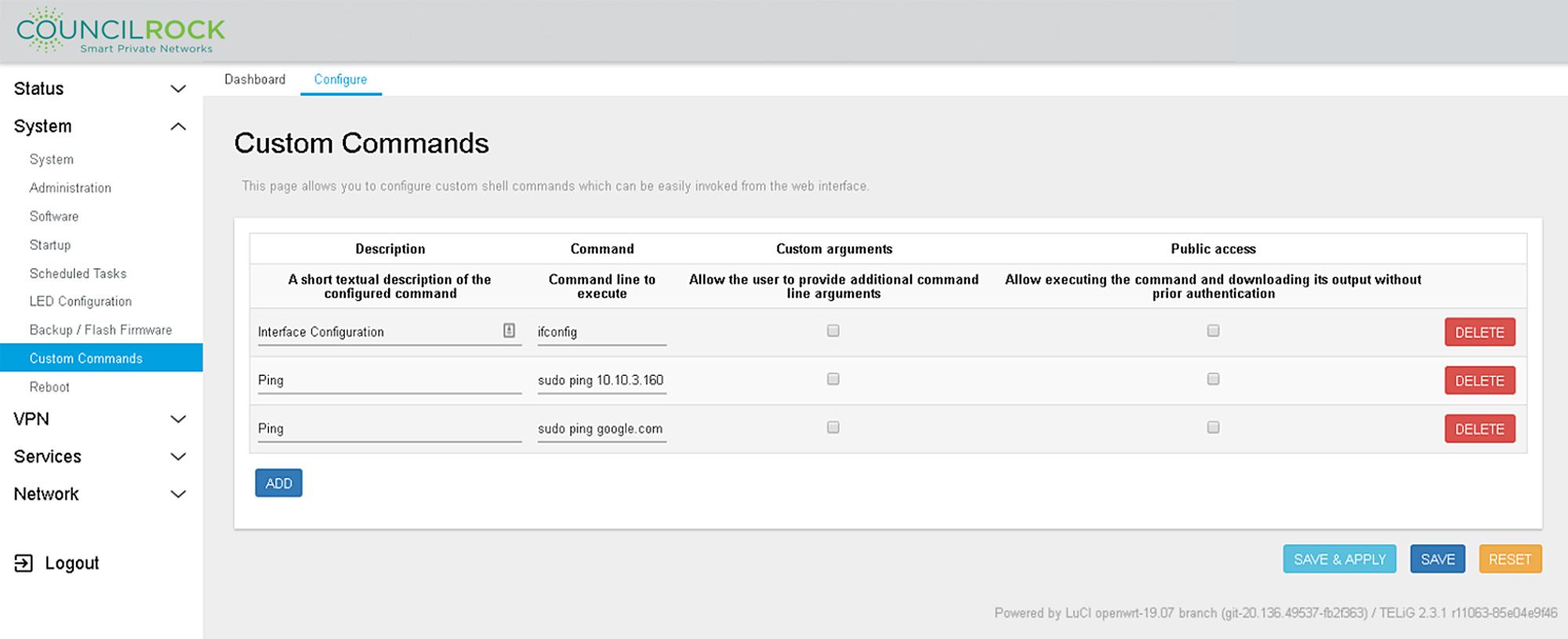
The Configure tab lets the user add new custom commands and edit and delete existing ones.
Important
Custom Commands are intended only for Advanced Users.
 |
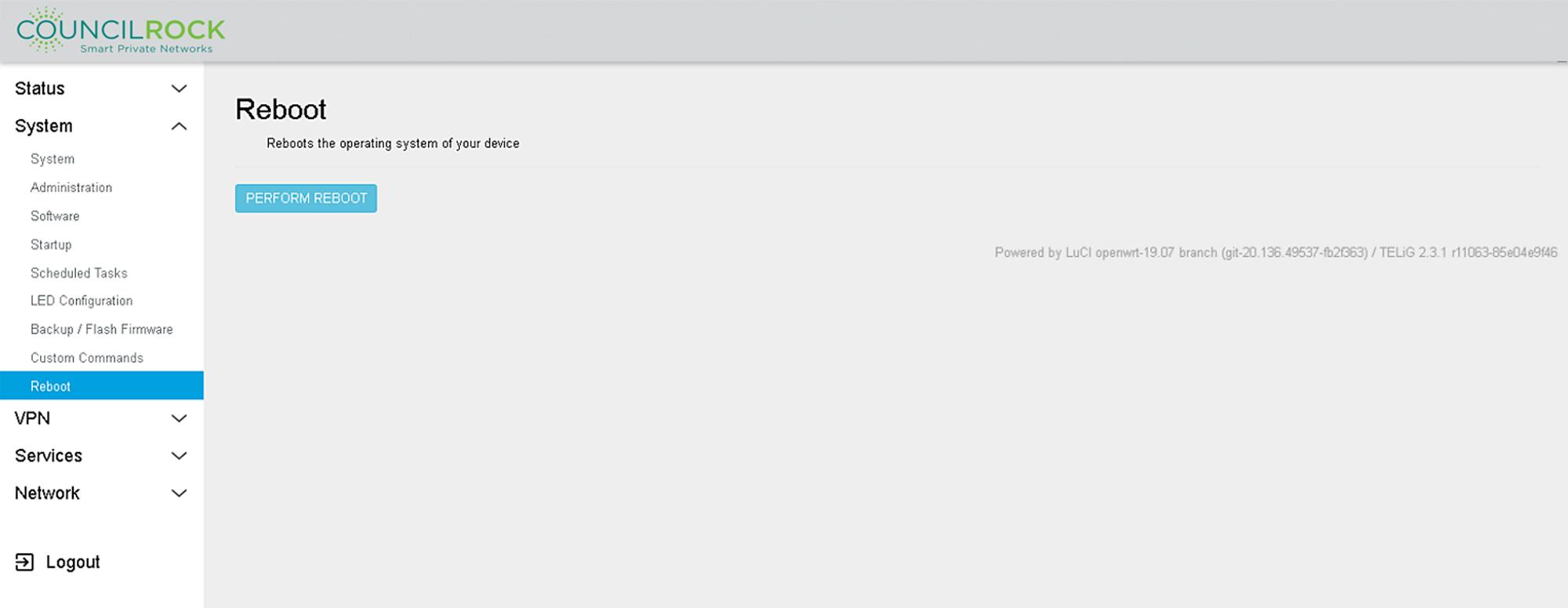
Reboot
Lets the user perform a soft reboot, which restarts the unit and all components without removing power.
 |
VPN
The VPN menu lets the user configure Virtual Private Network (VPN) settings using IPSec and OpenVPN. For details on these see two VPN options see https://www.strongswan.org/ and https://openvpn.net/.
IPSec
Under IPSec there are two main tabs. Status shows the status of all active IPSec configurations and Config lets the user configure IPSec Connections, Tunnels, and Ciphers.
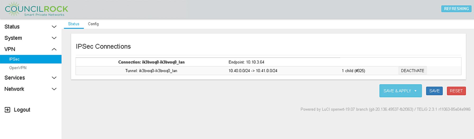 |
Figure 56: VPN > IPSec: Status
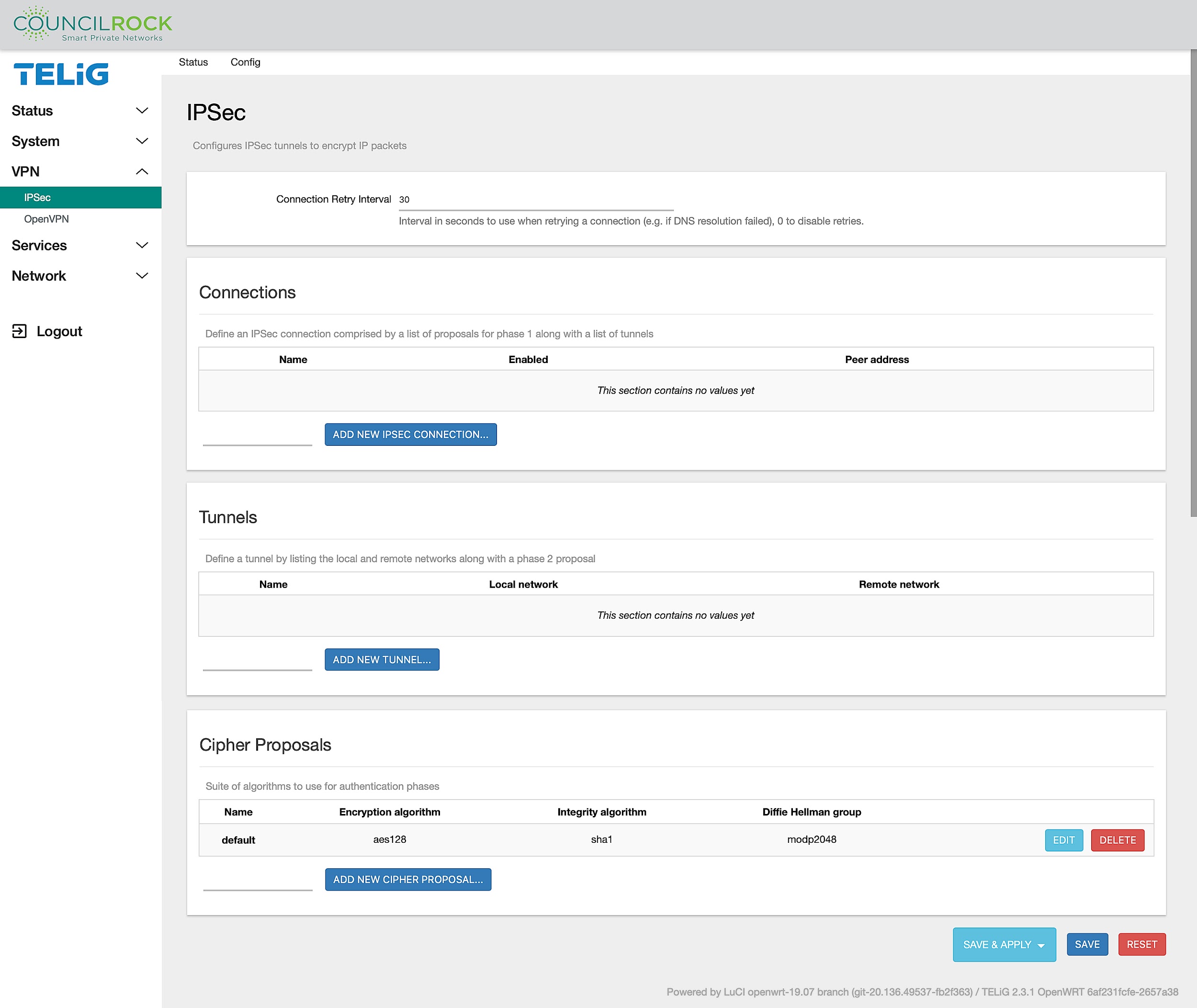 |
Figure 57: VPN > IPSec: Config
NOTE: VPN > IPSec: Configure window is the same as the main IPSec window
IPSec is a secure network protocol for encrypting communications between two points, the client and server. To create a configuration there are three steps:
define the cipher proposal for authentication
define the tunnel parameters for encryption and
create the vpn session.
In the cipher proposal window, the suite of algorithms to use for authentication phases
parameters are defined: the encryption algorithm, the integrity algorithm and the Diffie Hellman group. Supported options are listed in the drop-down menus.
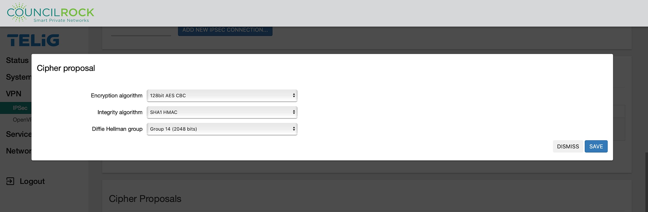 |
Figure 58: IPSec Cipher proposal
In the Tunnels configuration window, the next set of parameters define the local and remote networks along with a phase 2 proposal. These settings define the networks of the two ends of the tunnel, and the authentication method is selected (pre-shared key or X.509 certificates).
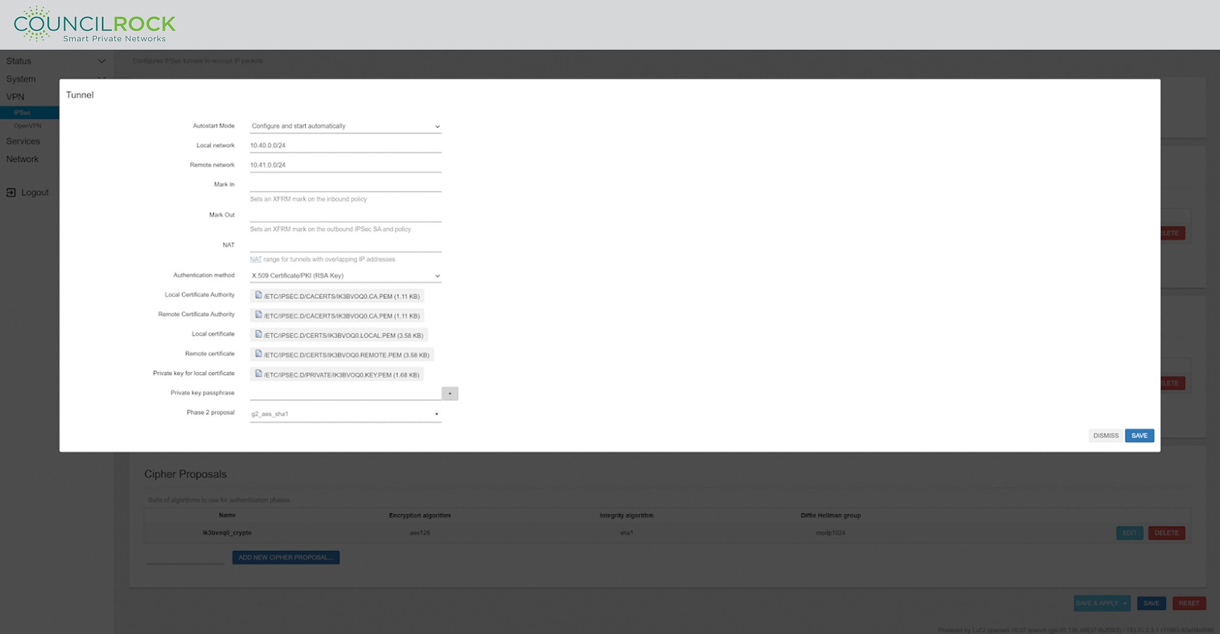 |
Figure 59: IPSec Tunnel configuration
The last step in setting up a VPN with IPSec encryption is defined in the Connections window. Here, peer network information (detailing the other end of the VPN tunnel) is entered, and the Cipher (Phase 1) Proposal and Tunnel are selected.
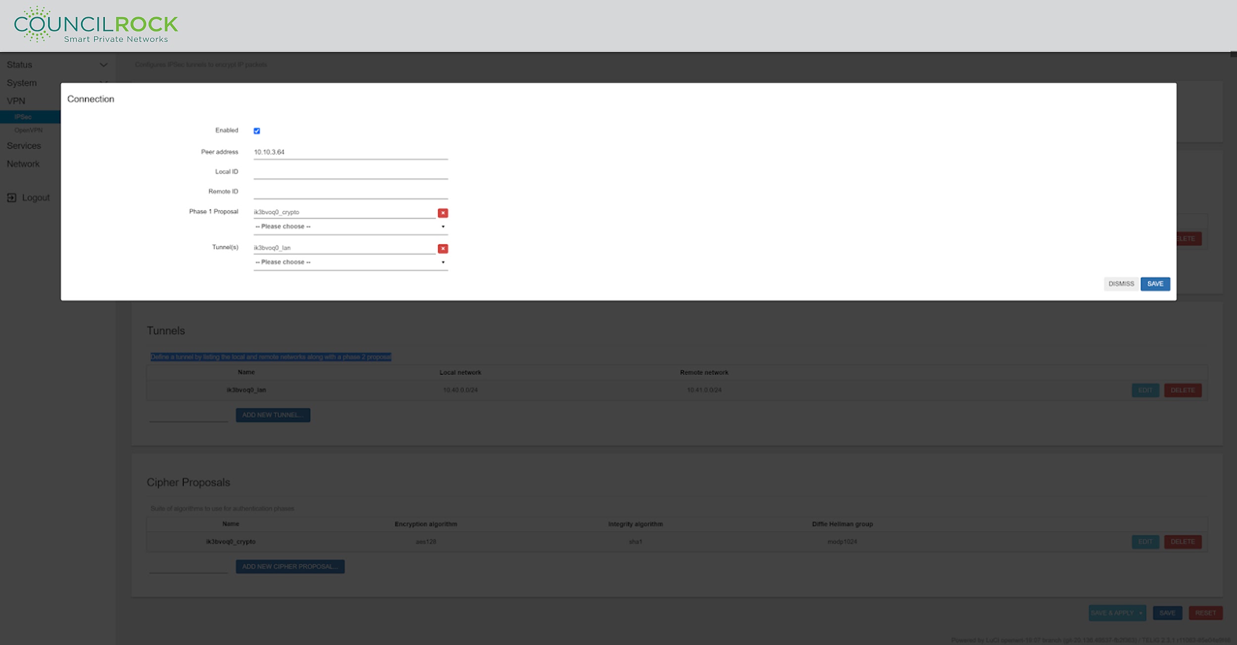 |
Figure 60: IPSec Connection configuration
OpenVPN
OpenVPN is an open-source VPN protocol that executes virtual private network (VPN) techniques for producing safe site-to-site or point-to-point connections in remote access facilities and bridged or routed configurations.
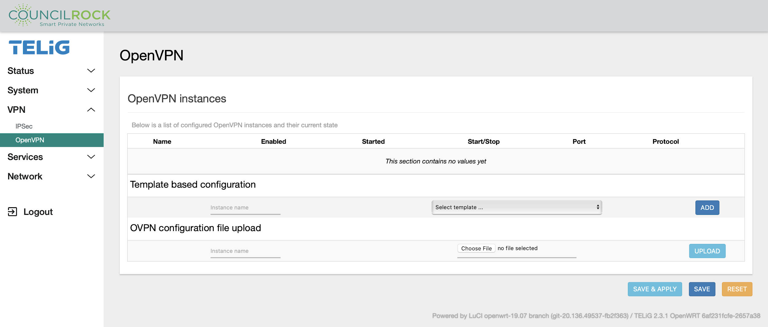
The OpenVPN menu displays a list of configured VPNs and their current states and allows the user to enable, start/stop, add, edit, or delete VPNs.
Create a new configuration with the Template-based configuration dialog by giving the new configuration a name, selecting a template, and clicking ADD. The new configuration appears in the OpenVPN Instances list and can be edited by clicking EDIT.
OpenVPN Templates provided are:
Client configuration for an ethernet bridge VPN populates basic settings for a client VPN session where the IP network of the server will be extended to the tunnel interface assigned to this VPN session. The kernel virtual network device is set to TAP which is an Ethernet level (layer 2) and acts like a switch.
Client configuration for a routed multi-client VPN populates basic settings for a client VPN session where the kernel virtual network device is set to TUN, which works at network level (layer 3) and routes packets on the VPN
Simple client configuration for a routed point-to-point VPN populates basic settings to set a TUN kernel network device to create a client VPN connection to connect to a server in a point to point configuration. Traffic needs to be routed by the server and the client independently.
Server configuration for an ethernet bridge VPN populates basic configuration to setup a server to allow clients to connect setting the kernel network device to TAP.
Server configuration for a routed multi-client VPN populates basic configuration to setup a server to allow clients to connect setting the kernel network device to TUN. The clients get network configuration settings and routes from the server
Simple server configuration for a routed point-to-point VPN populates basic configuration settings to set the E1500as a server VPN configuration to connect to only one client. The kernel network device is set to TUN.
Configuration files for these templates are shown below:
#
# Ethernet bridge client
#
config openvpn_recipe client_tun
	option _description	"Client configuration for an ethernet bridge VPN"
	option _role		"client"
	option client		"1"
	option dev 		"tap"
	option remote		"vpnserver.example.org 1194"
	option ca 		"ca.crt"
	option cert		"my_client.crt"
	option key 		"my_client.key"
	option dh 		"dh1024.pem"
	option ns_cert_type	"server"
	option keepalive	"10 120"
	option comp_lzo		"1"
	option nobind		"1"
#
# Routed client
#
config openvpn_recipe client_tun
	option _description	"Client configuration for a routed multi-client VPN"
	option _role		"client"
	option client		"1"
	option dev 		"tun"
	option remote		"vpnserver.example.org 1194"
	option ca 		"ca.crt"
	option cert		"my_client.crt"
	option key 		"my_client.key"
	option dh 		"dh1024.pem"
	option ns_cert_type	"server"
	option keepalive	"10 120"
	option comp_lzo		"1"
	option nobind		"1"
#
# Routed point-to-point client
#
config openvpn_recipe client_tun_ptp
	option _description	"Simple client configuration for a routed point-to-point VPN"
	option _role		"client"
	option dev		"tun"
	option remote 		"mypeer.dyndns.org"
	option port 		"1194"
	option ifconfig		"10.0.0.2 10.0.0.1"
	option secret		"shared-secret.key"
	option nobind		"1"
#
# Multi-client ethernet bridge server
#
config openvpn_recipe server_tun
	option _description		"Server configuration for an ethernet bridge VPN"
	option _role			"server"
	option dev			"tap"
	option port			"1194"
	option server_bridge 		"192.168.1.1 255.255.255.0 192.168.1.128 192.168.1.254"
	option ca			"ca.crt"
	option cert 			"server.crt"
	option key 			"server.key"
	option dh 			"dh1024.pem"
	option client_to_client		"1"
	option keepalive		"10 120"
	option comp_lzo			"1"
#
# Routed multi-client server
#
config openvpn_recipe server_tun
	option _description		"Server configuration for a routed multi-client VPN"
	option _role			"server"
	option dev			"tun"
	option port			"1194"
	option server			"10.0.100.0 255.255.255.0"
	option ca			"ca.crt"
	option cert 			"server.crt"
	option key 			"server.key"
	option dh 			"dh1024.pem"
	option client_to_client		"1"
	option keepalive		"10 120"
	option comp_lzo			"1"
#
# Routed point-to-point server
#
config openvpn_recipe server_tun_ptp
	option _description	"Simple server configuration for a routed point-to-point VPN"
	option _role		"server"
	option dev		"tun"
	option port		"1194"
	option ifconfig		"10.0.0.1 10.0.0.2"
	option secret		"shared-secret.key"
New VPNs can be uploaded from an OpenVPN configuration file, or by using one of the provided VPN templates. Note that when using template configuration, the user must edit the VPN after creation to provide the required information. However, this option is only for client configurations.
Use the OVPN configuration file upload dialog to name the new configuration and click UPLOAD. The new configuration appears in the table.
SERVICES
The Services submenus give access to the following settings:
Serial Gateway - Includes drop down options for Gateway types:
Distributed Network Protocol (DNP3) Gateways
Modbus Gateways - Modbus is a standard industrial Programmable Logic Controller (PLC) communication protocol over a serial interface.
QoS over Nftables - Quality of Service (QoS) controls packet flows based on user defined priorities.
SNMP - Simple Network Management Protocol (SNMP) is an Internet Standard protocol for device management over IP networks. SNMPD is the Linux-based SNMP agent that binds to a port and listens for requests from SNMP management software.
Note
To configure the gateway for Modbus, select Gateway: Modbus. At "Modbus Host Address," set the unit's IP address. 0.0.0.0 can be used here to bind all network interfaces, and 127.0.0.1 can be used to bind only to the loopback adapter. An interface's IP address can be specified here to bind only to that interface. Set the "Master IPv4/IPv6" address to the unit's address to restrict connections from only this address. This opens the socket on port 502, allowing Modbus communication.
Serial Gateways
Allows the user to set the serial communication protocol for the Serial A interface. The protocols supported by this interface are RS232, RS485 Half Duplex, and RS422/RS485 Full Duplex. The table below shows a basic comparison between these three protocols.
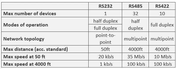 |
The Serial B interface only supports the RS232 protocol.
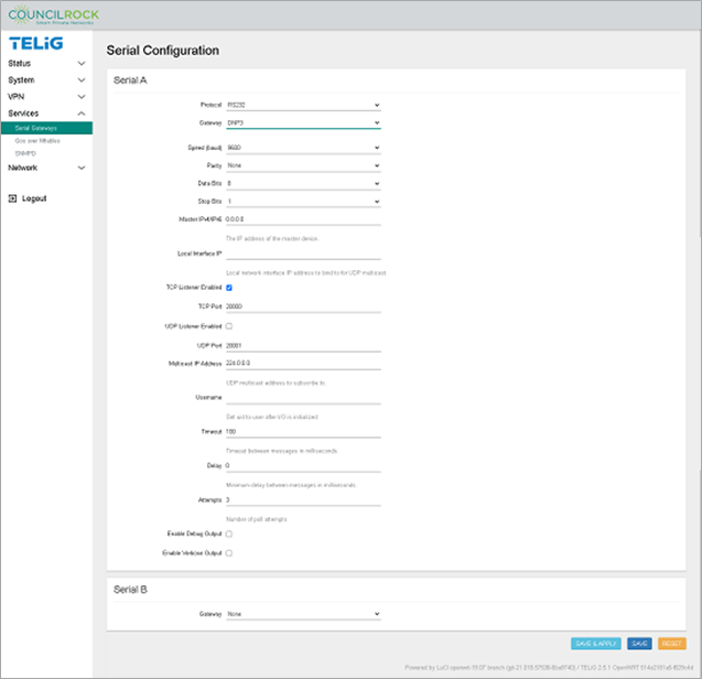 |
Note
on serial output error logging: For debug level logs, use the checkbox for "Enable Debug Output." For the most detailed error logs, use "Enable Verbose Output." While the interface allows both checkboxes to be selected, remember that verbose is the highest log level possible, and that debug logging is typically a subset of verbose logging. Therefore, it is advised that the user select either of these options but not both.
QoS over Nftables (Quality of Service)
This menu controls QoS at the packet level. It lets the user set Upload and Download Rate Limits to prioritize network traffic for each system interface. Rate Limits can be created to match traffic based on source IP address. Existing classification rules can be edited or deleted.
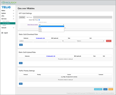
NFT-QoS Settings > Limit Rate contains settings for Download and Upload rate limits. Select the Limit Enable checkbox. By selecting Limit Type: Static, the user can set default DL/UL limit rates in bytes/s, Kbytes/s, or Mbytes/s. By selecting Limit Type: Dynamic, the user can set default DL/UL bandwidth limits in Mbps across a specified target Network using IPv4 or IPv6 addresses in CIDR notation. Individual IP address(es) can be added to a whitelist to bypass default limit rates when using either Limit Type by entering a whitelisted address and clicking the "+" button.
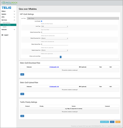 |
NFT-QoS Settings > Traffic Priority contains the interface selector fro which QoS Traffic Priorities can be configured. Select the Enable Traffic Priority checkbox. Select the Default Network Interface from the dropdown.
If the Traffic Priority Settings section is not visible, click Save & Apply. Continue to Traffic Priority Settings.
Static QoS - Download Rate / Statis QoS - Upload Rate sections are configurable when the Limit Rate is enabled. These sections allow the user to set Download / Upload rates for specific IP address(es). Click the ADD button and enter each hostname, IP address, MAC (optional) and Limit Rates in bytes/sec, Kbytes/sec, or Mbytes/sec. These Static QoS Rates are configurable in either Limit Type: Static or Limit Type: Dynamic (described in the Limit Rate settings above).
 |
Traffic Priority Settings section lets the user configure traffic priority by protocol and service. Click the ADD button and select a protocol (TCP, UDP, UDP-Lite, SCTP, or DCCP), priority (1 is highest), service (telnet, http, https, or a port number - multiple entries are possible, separated by a comma), and an optional comment. For multiple protocols, click the ADD button and repeat as needed. Click Save & Apply.
Note
When Limit Enable and/or Enable Traffic Priority are disabled, the corresponding Static Rates and/or Traffic Priority settings are not displayed until after clicking Save & Apply. Likewise, if Limit Enable and/or Enable Traffic Priority are enabled, their corresponding settings will not appear in the display until after clicking Save & Apply. If either option is disabled and later re-enabled, any settings the user has previously configured will be available as previously configured.
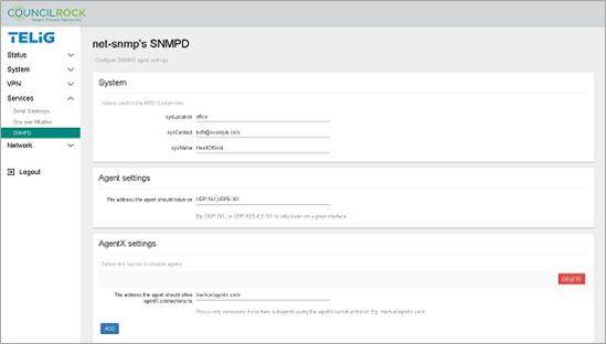
SNMPD
This menu provides Simple Network Management Protocol (SNMP) configuration via SNMP agents, SNMP traps, and SNMP informs, to manage the device over the network. SNMP is implemented via the Linux daemon net-snmpd. For more information on configuring SNMPD, see http://net-snmp.sourceforge.net/wiki/index.php/Snmpd.
 |
NETWORK
Interfaces
Displays information on and allows the configuration of the unit’s network interfaces. Each interface is listed with information including protocol, uptime, MAC address, transmitted and received data, and IPv4/IPV6 address and netmask (if applicable). The user can add / edit / delete interfaces and stop or restart active interfaces.
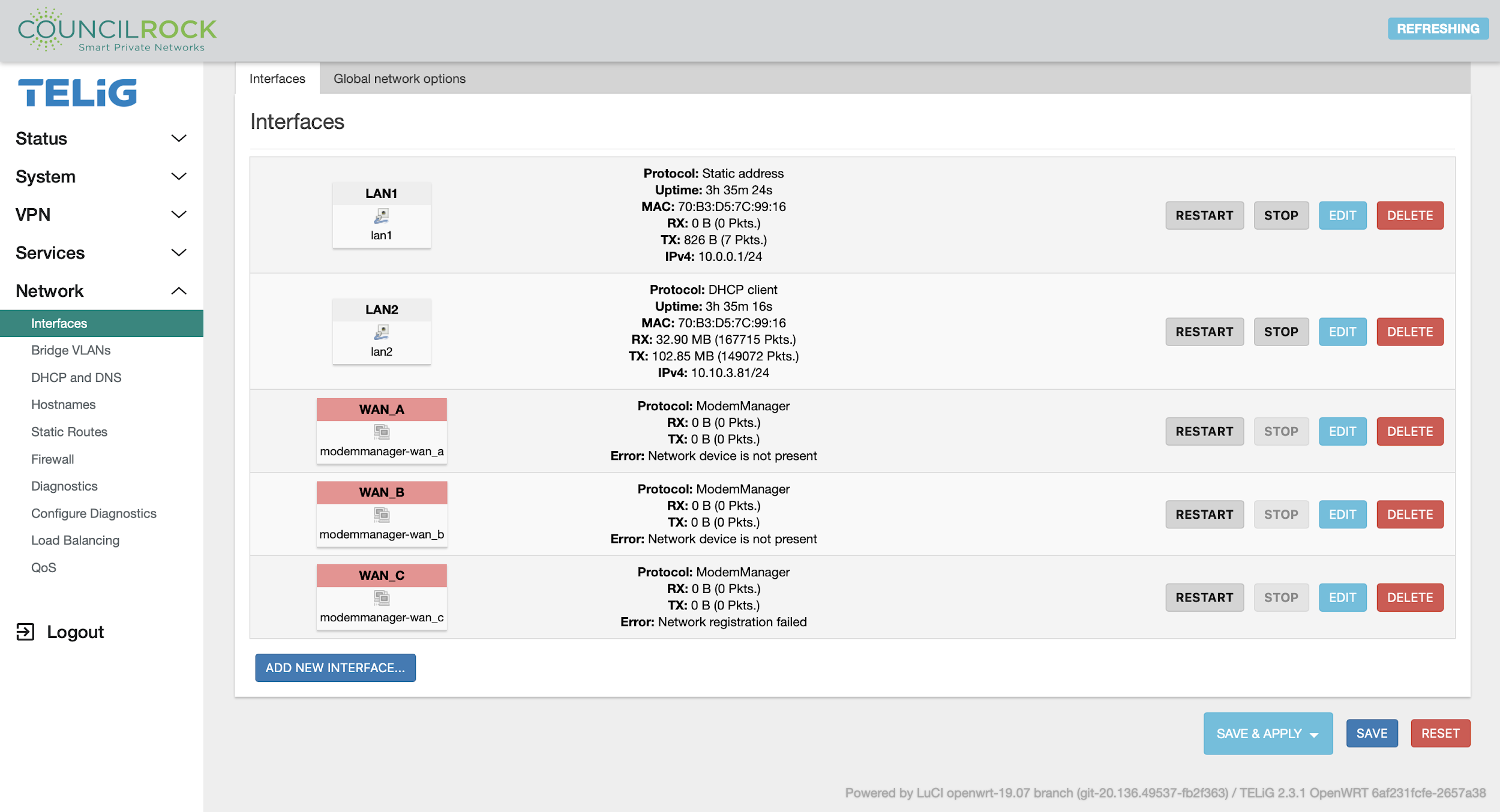 |
To add interfaces, enter a name, select a protocol, and select the physical interface (multiple interfaces if bridging). Additional options can be accessed by editing the interface once created, such as the protocol to use and whether to bring up the interface automatically on boot.
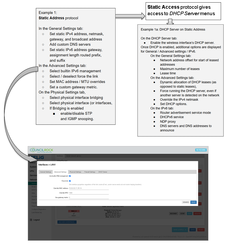
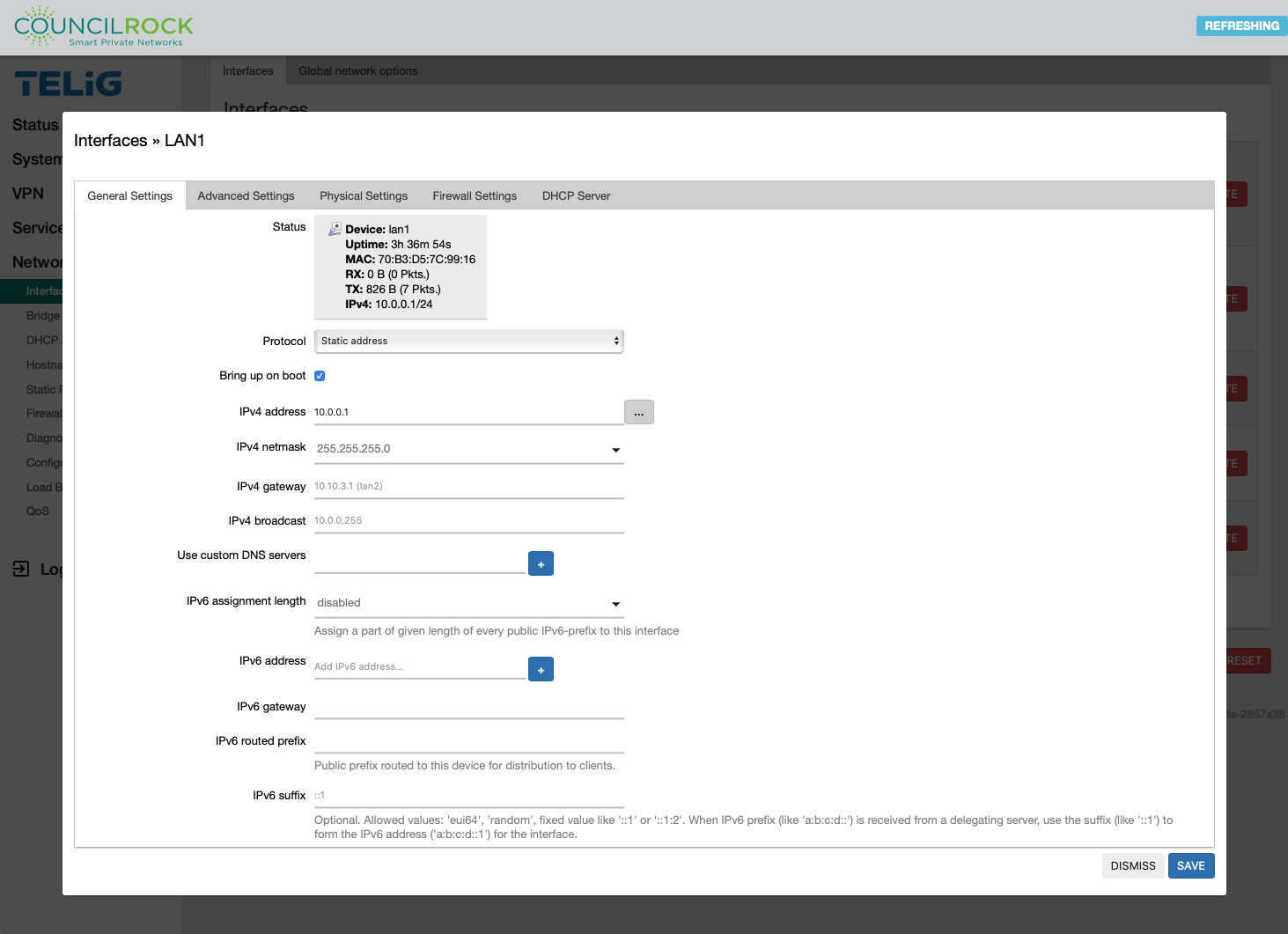
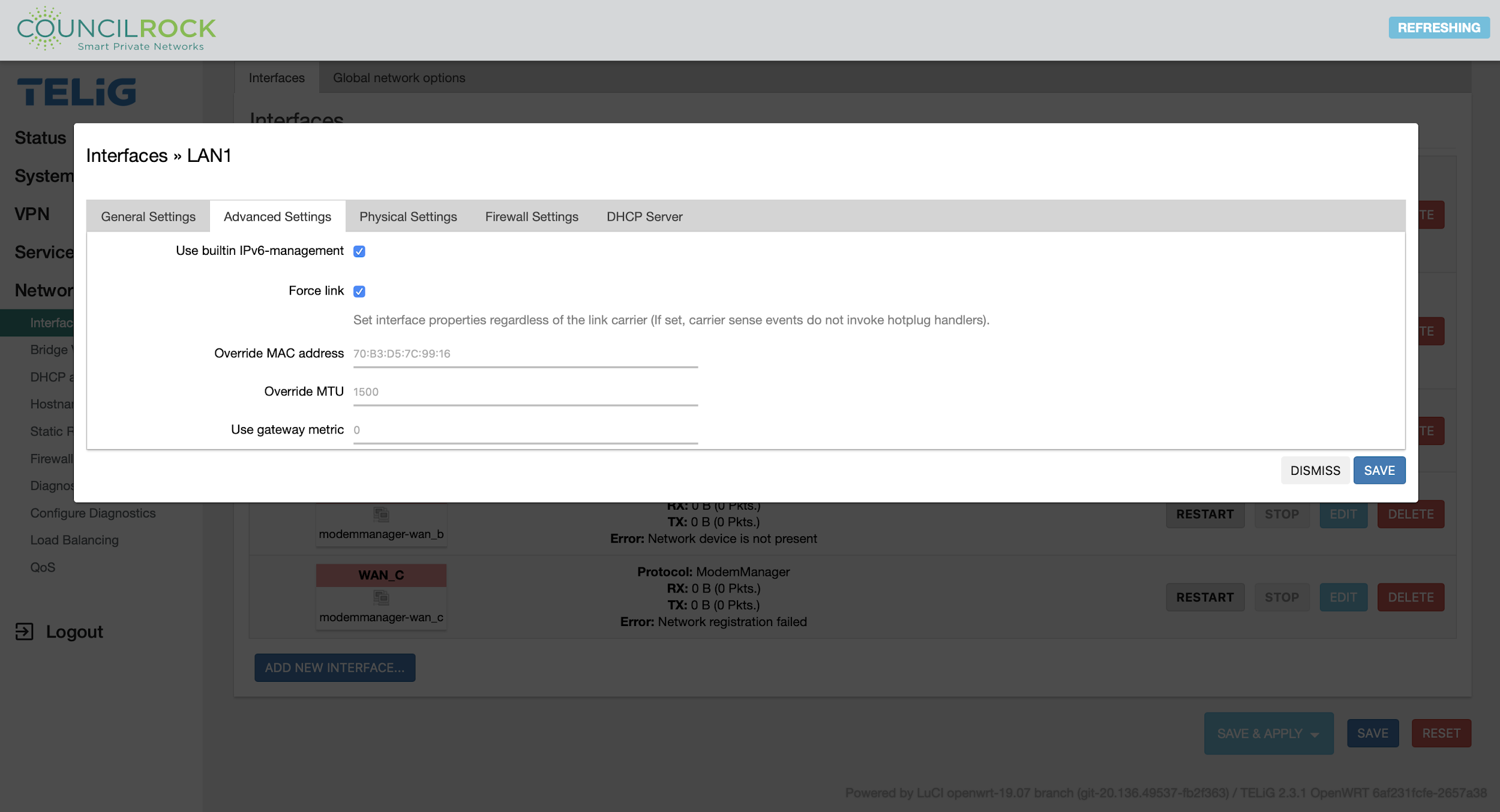
Available Options on the Interface editing dialogue vary depending on the selected protocol.
 |
 |
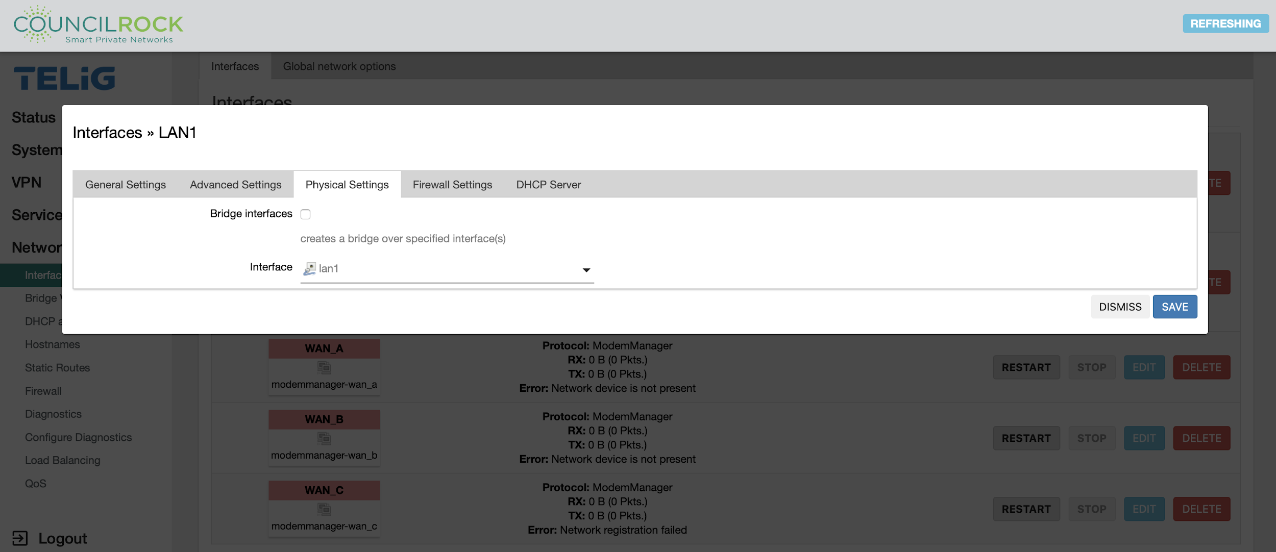
On the Physical Settings tab, the user can select whether to bridge physical interfaces, and select the physical interface (or interfaces, in the case of a bridge). If bridging is enabled, the user can enable/disable STP and IGMP snooping.
Bridging physical interfaces allows all ports in the bridge to act as a single network.
By enabling bridging, we can combine, for example, the WiFi (WLAN) interface(s) with the wired LAN ports to create a single logical network. We can also combine the two ethernet ports if desired.
 |
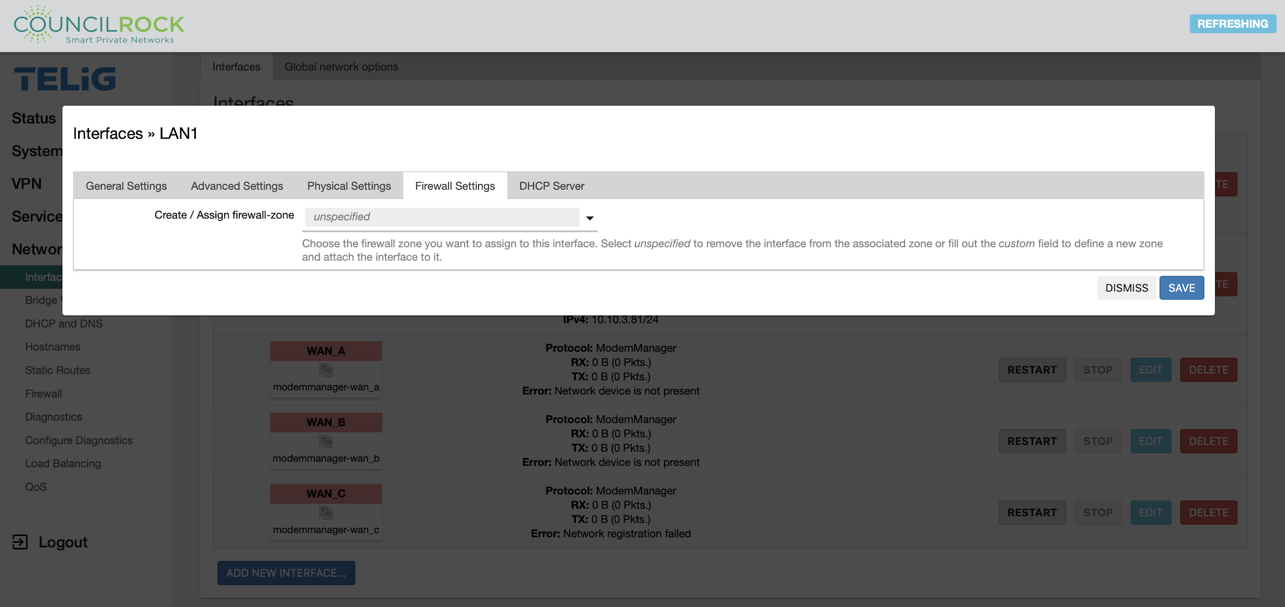
On the Firewall Settings tab, the user can create / assign the interface’s firewall zone.
The router Firewall collects interfaces into ‘firewall-zones’ to filter traffic. A firewall-zone can be configured to any set of interfaces but generally there are at least two zones:
lan - to collect LAN interfaces
wan - to collect WAN interfaces
A minimal router firewall configuration typically consists of one section, at least two firewall-zones (lan and wan), and one forwarding to allow traffic from LAN to WAN.
 |
On the DHCP Server tab, the user can set up the interface as a DHCP (Dynamic Host Control Protocol) Server.
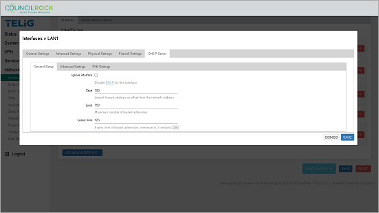
General Settings - Here the user can set the following General Options:
Ignore Interface - select the checkbox to bypass DHCP for this interface
Start - the starting number for address leases (the "N" in the IP address x.x.x.N)
Limit - the maximum number of addresses to lease
Lease Time - the time before leased addresses expire (for hours use 'h', for minutes use 'm'; the minimum allowable is 2m
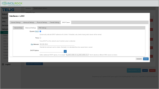
Advanced Settings - Here the user can set up the following Advanced DHCP options:
Dynamic DHCP - select the checkbox to automatically manage DHCP addresses. Leaving the box unchecked will limit IP address leases to clients with static addresses.
Force - select the checkbox to force DHCP on the interface even if another DHCP server is detected.
IPv4-Netmask - (default: 255.255.255.0) enter an IPv4 netmask here to override the default netmask; normally calculated from the subnet it serves.
DHCP-Options - lets the user configure other advanced DHCP options, such as use of an alternate gateway, DNS server and NTP server, or disable WINS. For a complete list of options, refer to: http://www.networksorcery.com/enp/protocol/bootp/options.htm
 |
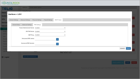
IPv6 Settings - Here the user can set up the following IPv6 DHCP options:
Router Advertisement-Service - from the dropdown list, select disabled, server mode, relay mode, or hybrid mode
DHCPv6-Service - from the dropdown list, select disabled, server mode, relay mode, or hybrid mode
NDP-Proxy - from the dropdown list, select disabled, relay mode, or hybrid mode
Announced DNS servers - add an IP address to the text box and click the '+' button to set the DNS server to be announced
Announced DNS domains - add an IP address to the text box and click the '+' button to set the DNS server domain to be announced.
From the OpenWRT manual:
OpenWrt features a versatile RA & DHCPv6 server and relay. Per default, SLAAC
(Stateless Address Autoconfiguration) and both stateless and statefule DHCPv6
are enabled on an interface. If there are any prefixes of size /64 or shorter
present, then addresses will be handed out from each prefix. If all addresses
on an interface have prefixes shorter than /64 then DHCPv6 Prefix Delegation is
enabled for downstream routers. If a default route is present the router advertises
itself as default router on the interface.

The system is also able to detect when there is no prefix available from an
upstream interface and can switch into relaying mode automatically to extend
the upstream interface configuration onto its downstream interfaces. This is
useful for putting the target router behind another IPv6 router which doesn’t
offer prefixes via DHCPv6-PD.
For more on IPv6 routing with OpenWRT, refer to: https://openwrt.org/docs/guide-user/network/ipv6/start#router_advertisement_dhcpv6
 |
Wireless (Available on “W” units)
Displays active wireless networks and associated stations. Wireless network interfaces can be enabled / disabled / restarted / added / edited / removed.
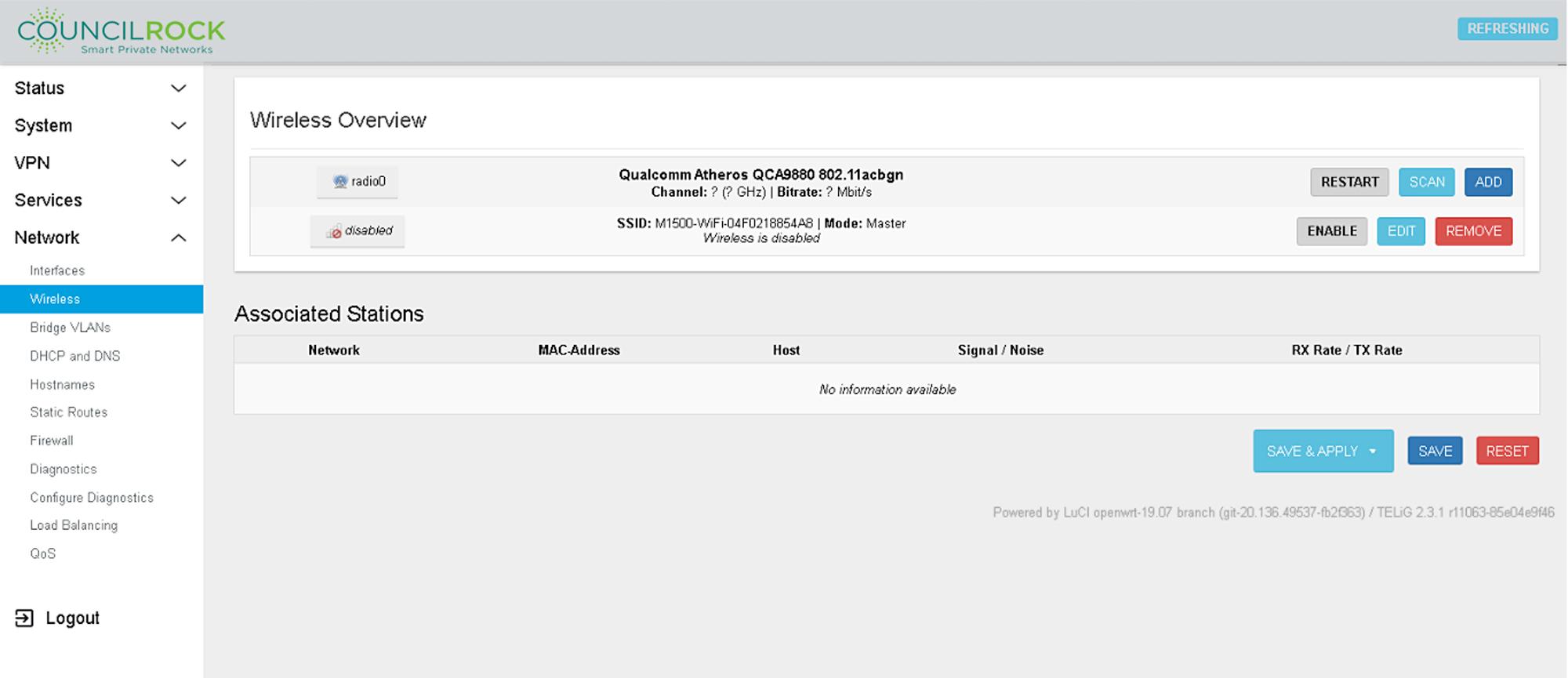 |
The Restart button can be used to restart the wireless interface.
The Scan button starts a network scan for detectable wireless networks, displaying signal strength, SSID (network name), encryption type, and other network information.
The Join Network button opens a dialogue to connect to a network. If the network is encrypted, authentication credentials are required to join.
When adding / editing a wireless network, the Edit wireless network dialogue is displayed. The General Setup tab (located on the top card of the Edit wireless network dialogue) lets the user enable or disable the network, select the frequency band and channel, and set maximum transmit power.
![Wireless > Wireless Network > General [Top Card]](image/161570f952a46d.png) |
The Advanced Settings tab (located on the top card of the Edit wireless network dialogue) allows the user to set a non-default country code, toggle allowing legacy 802.11b rates, set up distance optimization, change fragmentation and RTS/CTS thresholds, and set the beacon interval. The user can force 40MHz channels, bearing in mind that this is non-compliant with IEEE 802.11n-2009.
![Wireless > Wireless Network > Advanced [Top Card] and General Setup [Bottom Card]](image/161570f952e427.png) |
Configuration options available on the bottom card of the Edit wireless network dialogue vary depending on the wireless mode configuration.
A common configuration, for example, is to configure the unit as a wireless access point. To set this up, under the General Setup tab (located on the bottom card of the Edit wireless network dialog) use the following options:
Mode | Access Point |
|---|---|
ESSID | Network name as it appears on client devices |
Network | The network(s) to attach to the wireless interface |
Hide ESSID | Check to hide the network (requiring manual SSID entry to connect) |
WMM Mode | Check to enable WiFi Multimedia (WMM) mode (prioritizing multimedia packets for quality of service) |
Under the Wireless Security tab (located on the bottom card of the Edit wireless network dialog), the user can configure network security settings. Configuration options vary based on encryption type selected. We recommend using a strong security WPA2 encryption.
The most common encryption type is WPA2-PSK password-based. After selecting “WPA2-PSK (strong security)” from the dropdown, the user can enter the Key (password), and optionally enable WPS push button authentication.
![Wireless > Wireless Network > Wireless Security [Bottom Card]](image/161570f95326c2.png) |
Alternatively, if a RADIUS authentication server exists on the network, the user can select “WPA2-EAP (strong security)” from the dropdown list to set up RADIUS authentication. Follow these steps to set up RADIUS:
Enter the RADIUS server's IP address for Radius-Authentication-Server, and the port number for Radius-Authentication-Port (if different from the default).
Add the pre-configured password to Radius-Authentication-Secret.
If the RADIUS authentication system uses a different server for accounting, enter the server's IP address and port (if different from the default), as Radius-Accounting-Server and Radius-Accountint-Port.
Enter the accounting password as Radius-Accounting-Secret,.
If the DAE client differs from your RADIUS server, enter the DAE clent's IP address and port (if different from the default) as DAE-Client and DAE-Port, and the DAE client's password as DAE-Secret.
Optionally, set a NAS ID.
For both WPA2-PSK and WPA2-EAP encryption, the user has the option to select a cipher, and configure 802.11r fast translation, 802.11w management frame protection, and key reinstallation countermeasures.
Under the MAC-Filter tab (located on the bottom card of the Edit wireless network dialogue), the user can set up blacklist (do not allow) or whitelist (only allow) devices with specific MAC addresses.
![Wireless > Wireless Network > MAC-Filter [Bottom Card]](image/161570f953651c.jpg) |
Under the Advanced Settings tab (located on the bottom card of the Edit wireless network dialogue), the user can configure advanced settings for the wireless network such as preventing client to client communication and overriding the default wireless interface name.
![Wireless > Wireless Network > Advanced Settings [Bottom Card]](image/161570f953aa35.jpg) |
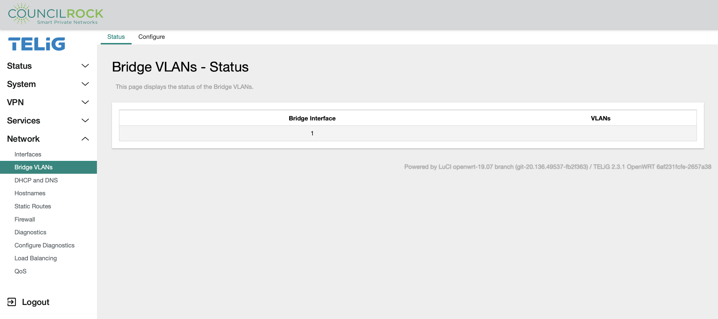
Bridge VLANs
Allows the user to configure groups of ports as ‘virtual LANs’
The Status tab displays the status of the bridge interfaces and VLANs.
 |
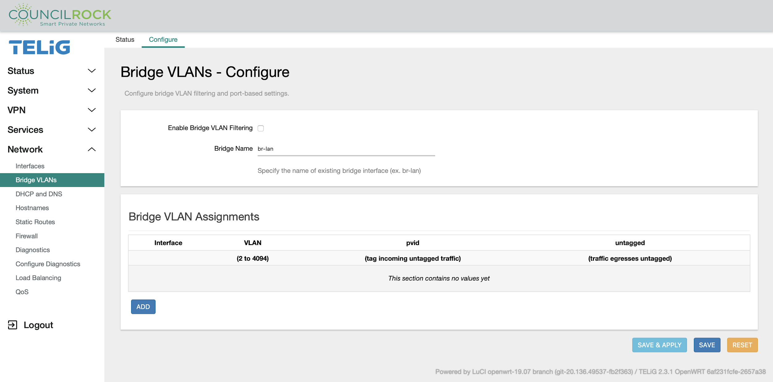
The Configure tab lets the user enable bridge VLAN filtering and specify a bridge interface to use, and to add, edit, and delete bridge VLAN assignments.
 |
DHCP and DNS
The DHCP and DNS menu lets the user configure Dynamic Host Configuration Protocol (DHCP) server and Domain Name System (DNS) forwarder options for local Network Address Translation (NAT) networks.
The General Settings tab allows the user to set the general behavior for the DHCP server and DNS forwarder.
 |
The Resolv and Hosts Files tab lets the user specify configuration files for the DHCP server, specify a DHCP lease file, specify a DNS resolve file, and specify additional hosts files (in addition to the default /etc/hosts).
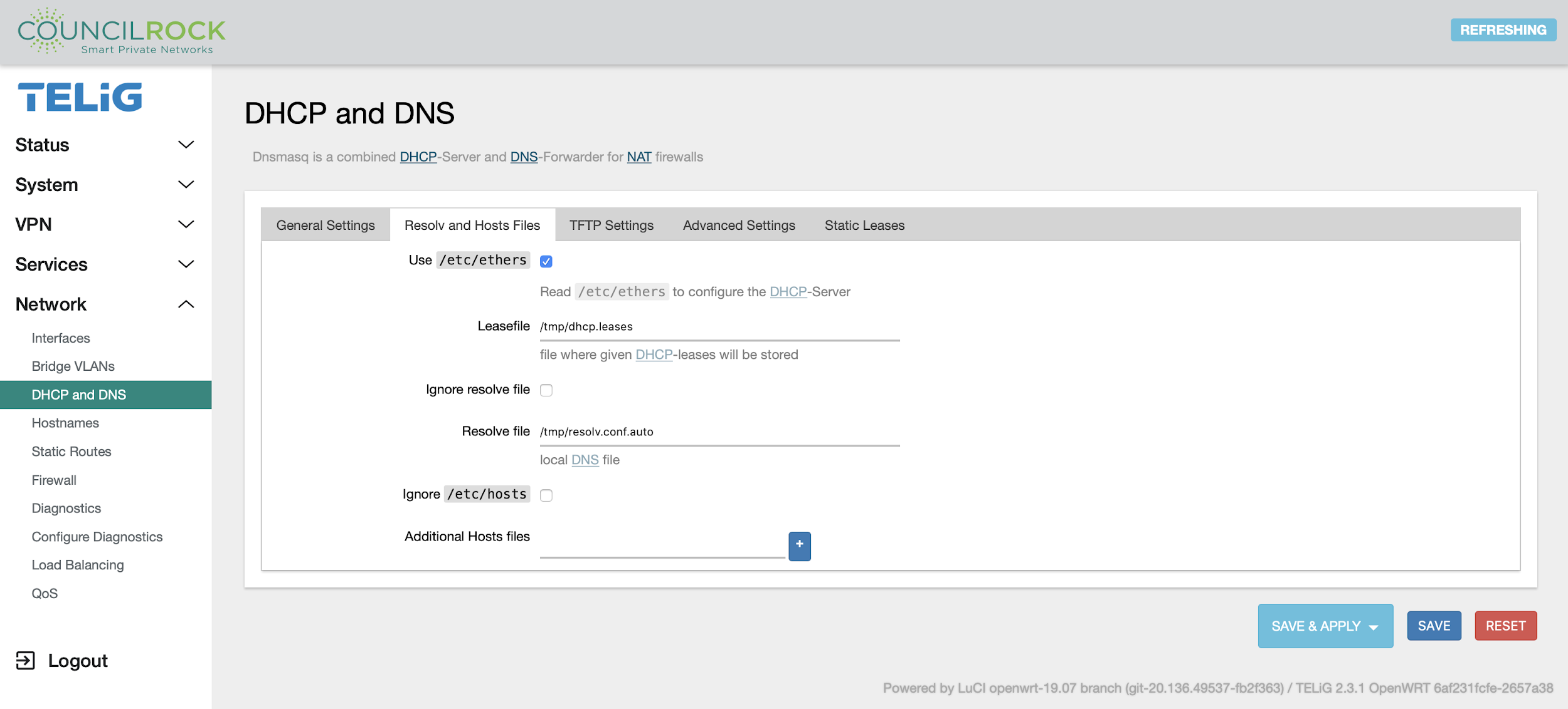 |
The TFTP Settings tab is to enable and configure the root directory for a TFTP server.
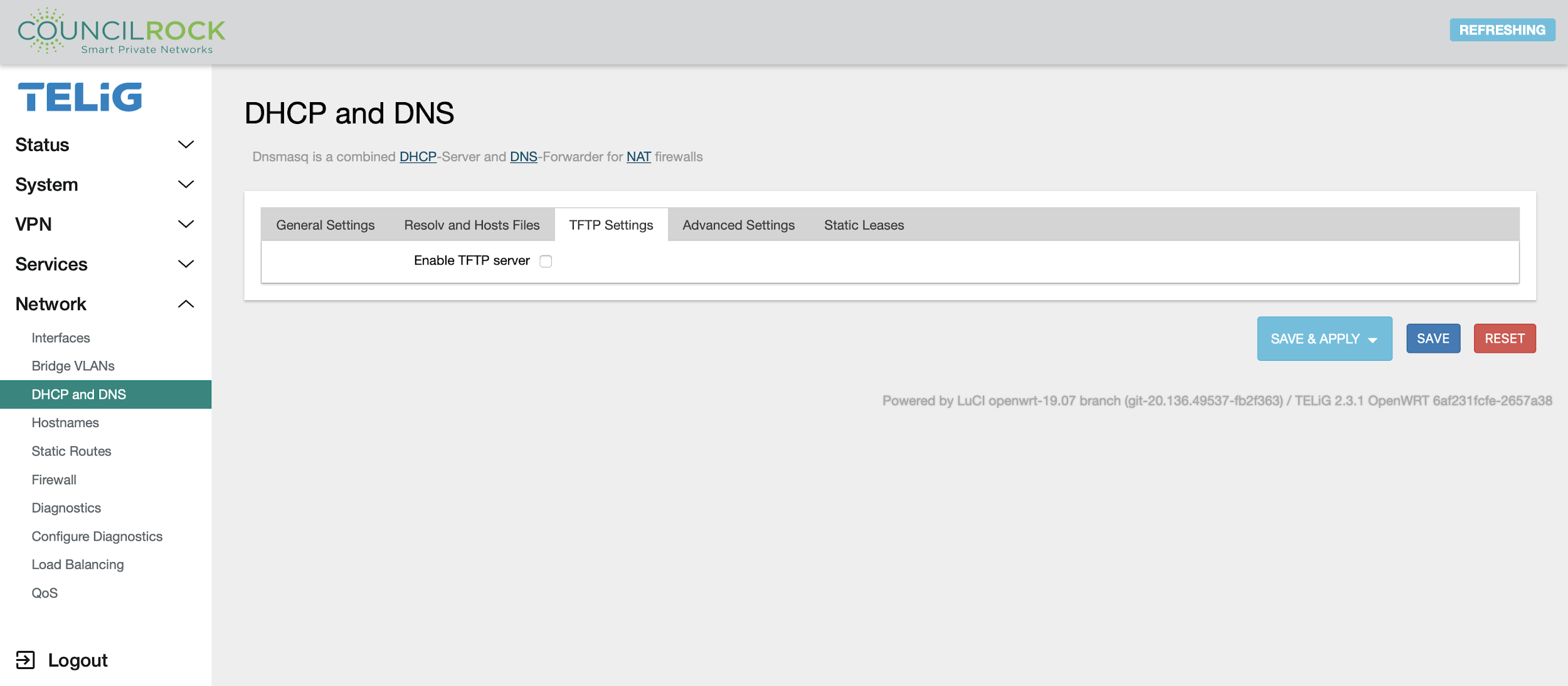 |
The Advanced Settings tab allows the configuration of additional behavior settings for the DHCP server and DNS forwarder.
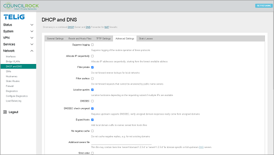 |
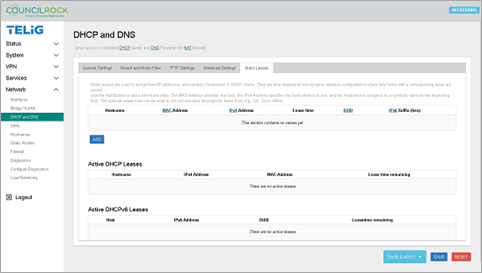
Finally, the Static Leases tab lets the user view, add, and edit static leases for DHCP clients as well as view active DHCP leases for IPv4 and IPv6 clients. Static DHCP leases can be configured with optional symbolic hostnames and custom lease times.
 |
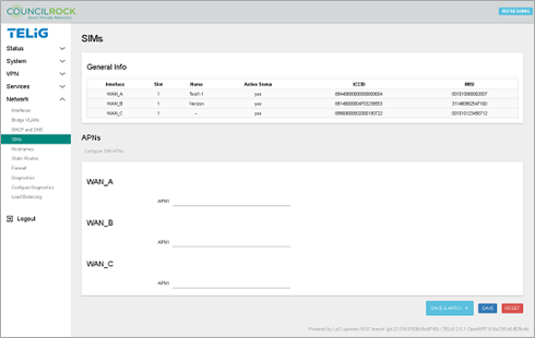
SIMs
The SIMs menu lets the user display current SIM card info in the General Info section. In the APNs section, users can set identifying APN numbers on installed SIM card(s) by entering the APN number in the applicable interface text box and clicking Save & Apply.
 |
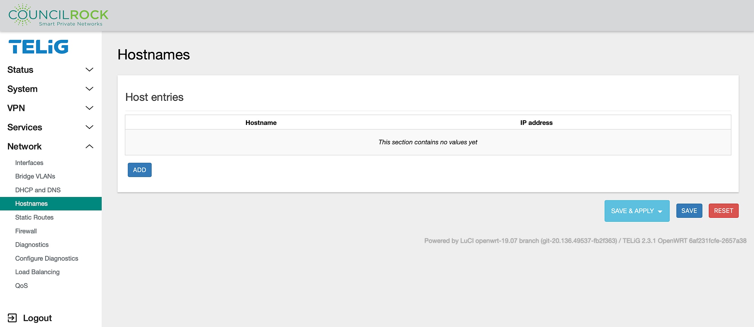
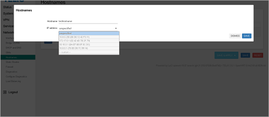
Hostnames
The Hostnames menu lets the user set up custom hostnames for IP addresses. You can add a new host entry, edit, or delete an existing entry by clicking the ADD button and entering a hostname then selecting an IP address from the dropdown menu, or you can edit or delete existing entries, and reorder entries by dragging them to another location in the list with the  icon.
icon.
 |
 |
Static Routes
Static routes provide one of the safest methods of Layer 3 connectivity. These are secure from route spoofing attacks because your router does not rely on routing information being sent and received from other routers. All the routing information is user controlled and locally configured.
Static routes are typically used where:
There are only a small number of destinations to configure
One or two paths exist to each destination
With static routes, the following is true:
A default route is used on the perimeter router to reach external resources
Specific internal routes are used to reach internal resources
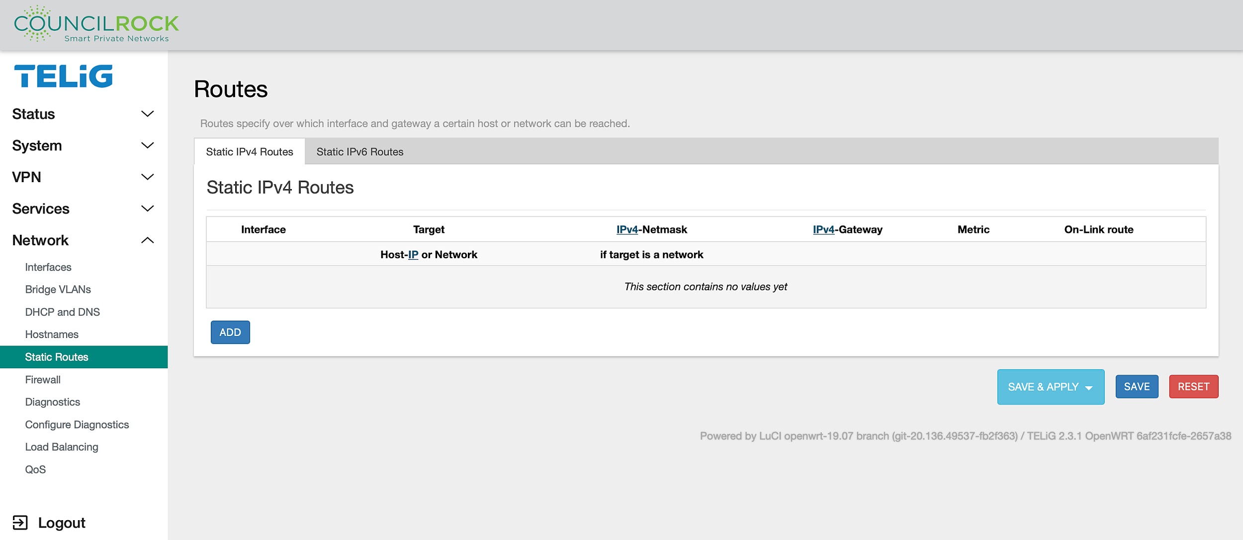 |
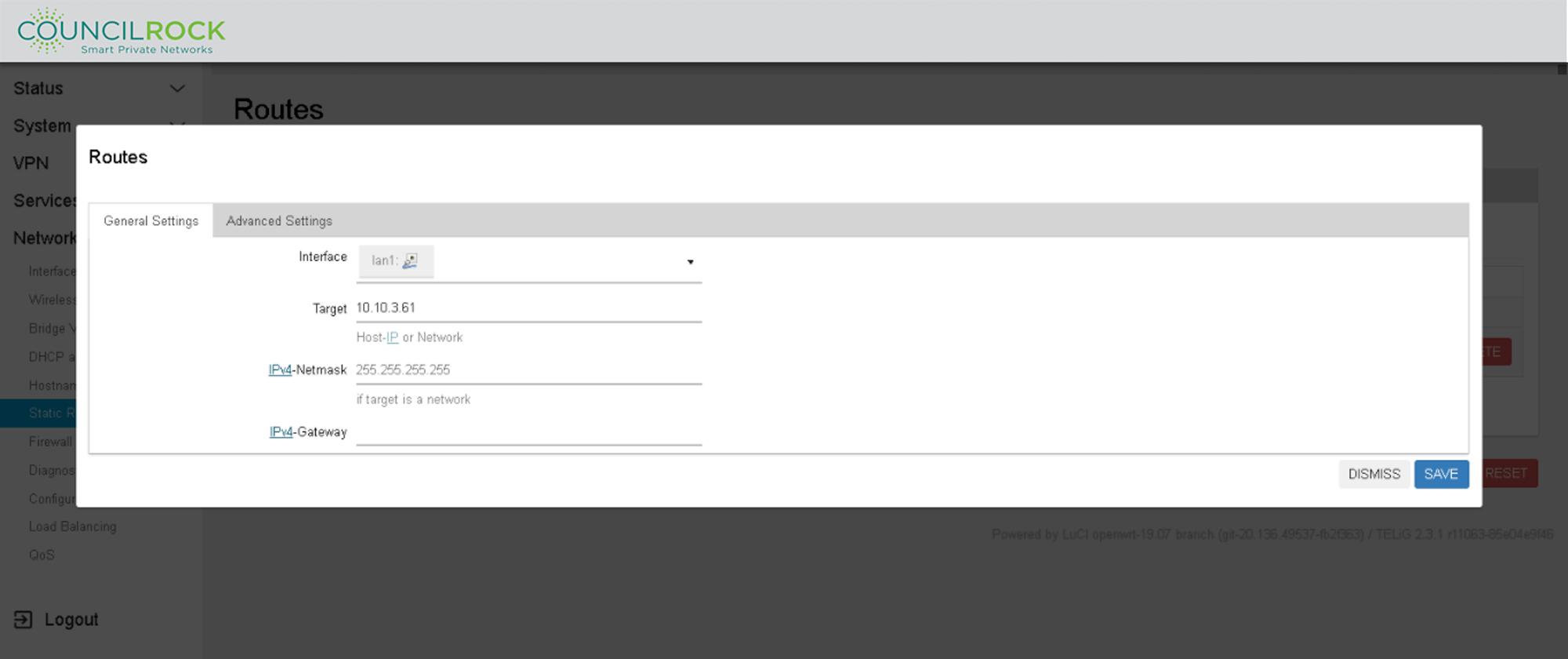
To add a route, click the ADD button. On new routes or when editing existing routes, the following settings are available:
GENERAL SETTINGS
Interface: Select the interface where the target network resides; defined interfaces will be selectable from the dropdown list.
Target IP: The address of the destination network.
Netmask: A mask that is applied to the Target IP that determines which IP addresses the route applies to. If omitted, 255.255.255.255 is assumed, which makes Target IP a host address.
Gateway: Defines where the router should send traffic. if omitted, the gateway from the parent interface is taken, if any. Otherwise, gateway creates a link scope route. If set to 0.0.0.0, no gateway will be specified for the route.
 |
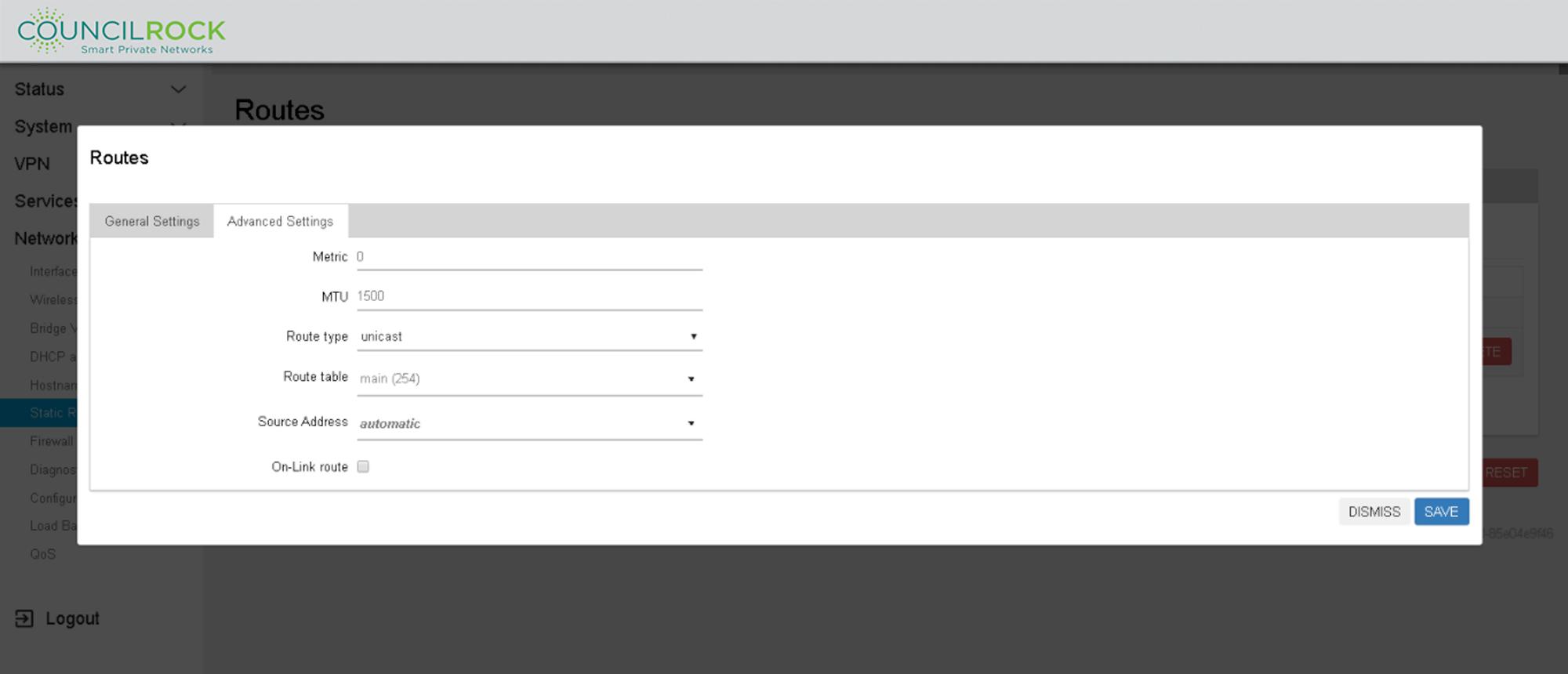
ADVANCED SETTINGS
Metric: (default = 0) is used as a sorting measure. If a packet that is about to be routed fits two rules, the one with the lower metric is applied.
MTU: (default = 1500) specifies the Maximum Transmission unit in Kb for this route.
Route Type: (default = unicast) specifies the behavior for the route. Options are:
unicast: The route entry is for a path to a single destination IP
local: The destination is assigned to this host. Packets are looped back and delivered locally.
broadcast: The destination is a broadcast address. Packets are sent as link broadcasts.
multicast: A special type used for multicast routing. It is not present in normal routing tables.
unreachable: These destinations are unreachable. Packets are discarded and the ICMP message 'host unreachable' is generated.
prohibit: These destinations are unreachable. Packets are discarded and the ICMP message 'communication administratively prohibited' is generated.
blackhole: These destinations are unreachable. Packets are discarded without a response.
anycast: These destinations are equivalent to local with one difference - such addresses are invalid when used as the source address of any packet.
Route Table: (default = main(254)) defines the table ID to use for the route. The special aliases local (255), main (254), and default (253) as well as 'custom' are selectable from the dropdown list. If 'custom' is used, enter a number ranging from 0 to 65535 directly in the dropdown.
Source Address: (default = automatic) is the preferred source address when sending to destinations covered by the target. Local IP addresses are selectable from a dropdown list, as well as a 'custom' field for entering IP addresses directly.
On-Link Route: (default = off) when enabled, the gateway is on link even if the gateway does not match any interface prefix.
 |
Firewall
The Firewall menu is for setting up Firewall Zones, Rules, and Port Forwarding.
The General Settings tab contains default Firewall settings and provides add / edit / delete functions for the listed Firewall Zones.
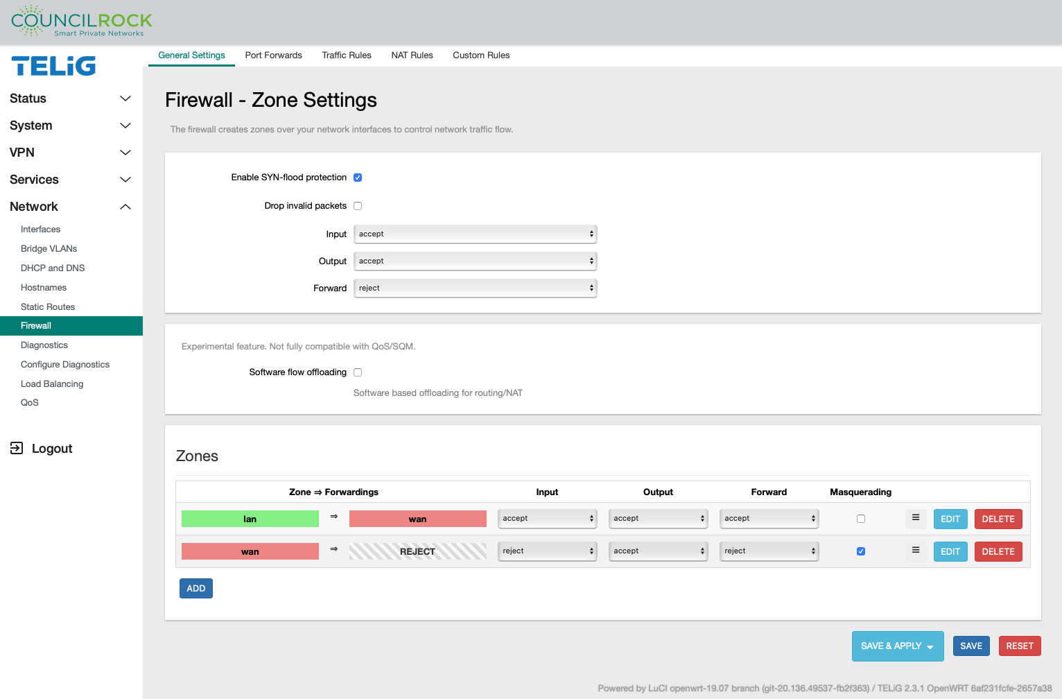 |
Note
Software flow offloading: This is a Linux kernel- based routing process using netfilter, allowing specific kernel modules to register callback functions to the networking stack. When a packet is received and its flow is not known, it is forwarded to the networking stack. If its flow is known, NAT translation (if any) is applied and it is forwarded to the appropriate port. As an experimental Linux feature, we do not recommend activating software flow offloading.
When creating a new firewall zone or editing an existing one, the Firewall - Zone Settings dialogue appears with the following submenus:
Firewall - Zone Settings > General Settings contains settings for:
Zone name
Zone input, output, and traffic forwarding behavior
Networks covered by the zone
Forwarding policy to and from the zone
Masquerading and MSS clamping.
Firewall - Zone Settings > Advanced Settings contains the settings to:
Restrict zone coverage
By device
By subnet
By IP family
Set Masquerading by source and/or destination subnets
Enable / disable logging.
Firewall - Zone Settings > Conntrack Settings contains settings for:
Toggling automatic conntrack helper assignment
Allowing “invalid” traffic for the zone.
Conntrack is a userspace command line program targeted at system administrators. It enables them to view and manage the in-kernel connection tracking state table.
Firewall - Zone Settings > Extra Iptables Arguments allows the user to set up raw source and destination arguments to the iptables command allowing finer control of firewall rules.
Important
Firewall Zone Extra IPTables Arguments are intended only for Advanced Users.
The Port Forwards tab displays existing port forwarding rules, and lets the user add / edit / delete Port Forwarding Rules. This configures the unit to forward traffic directed to a port on the device to another IP address and port.
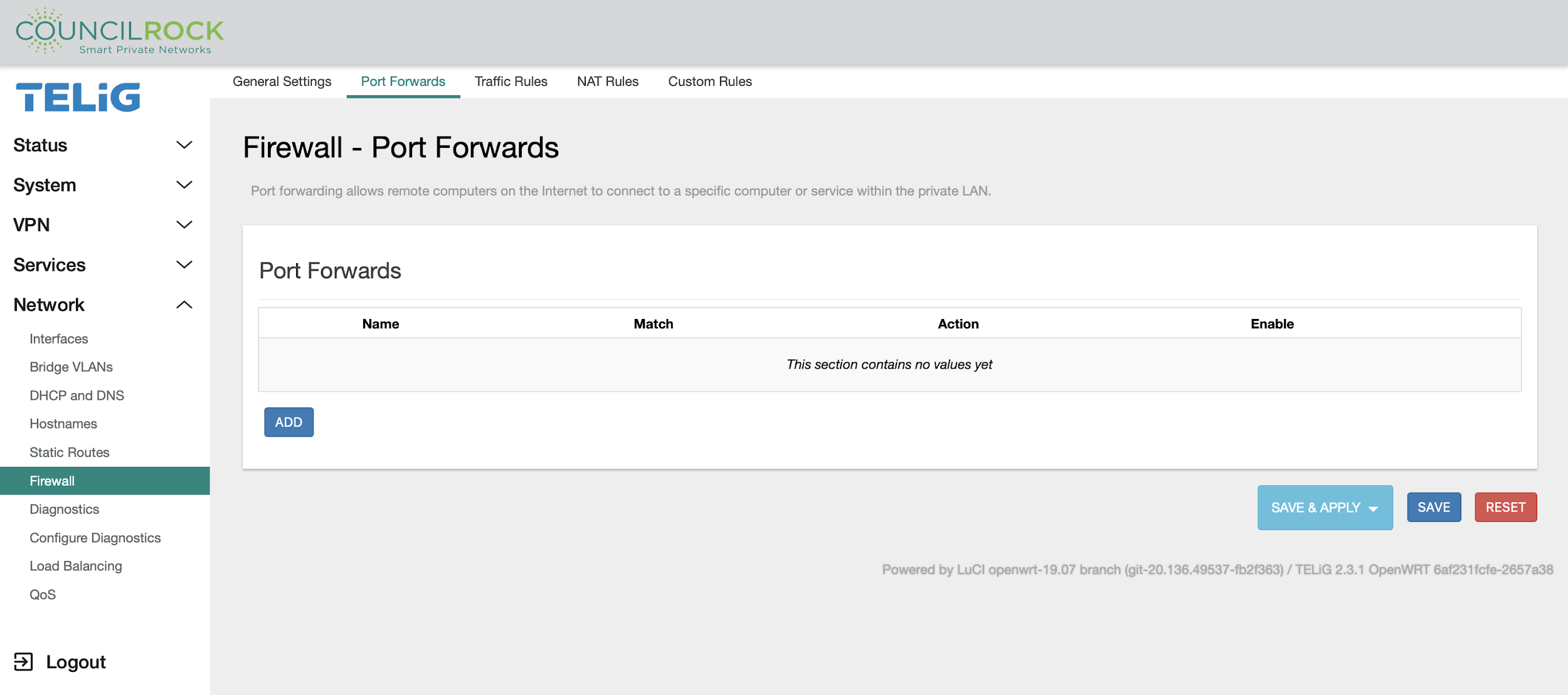 |
Important
Firewall Port Forwarding is intended only for Advanced Users.
When creating / editing a port forward, the Firewall - Port Forwards dialogue is displayed with the following submenus:
Firewall - Port Forwards > General Settings contains settings for:
Protocol
Source zone
External destination port
Destination zone
Internal destination IP address and port
Firewall - Port Forwards > Advanced Settings provides for further traffic restrictions by matching the forwarding rule to:
Source MAC address
Source IP address
Source port
External destination IP address
Advanced Settings are also provided for these cases (intended only for Advanced users):
Whether to use an internal or external IP address for reflected traffic
To specify additional matching configurations
To pass raw arguments to the underlying iptables command
The Traffic Rules tab displays existing traffic rules and provides add / edit / delete functionality.
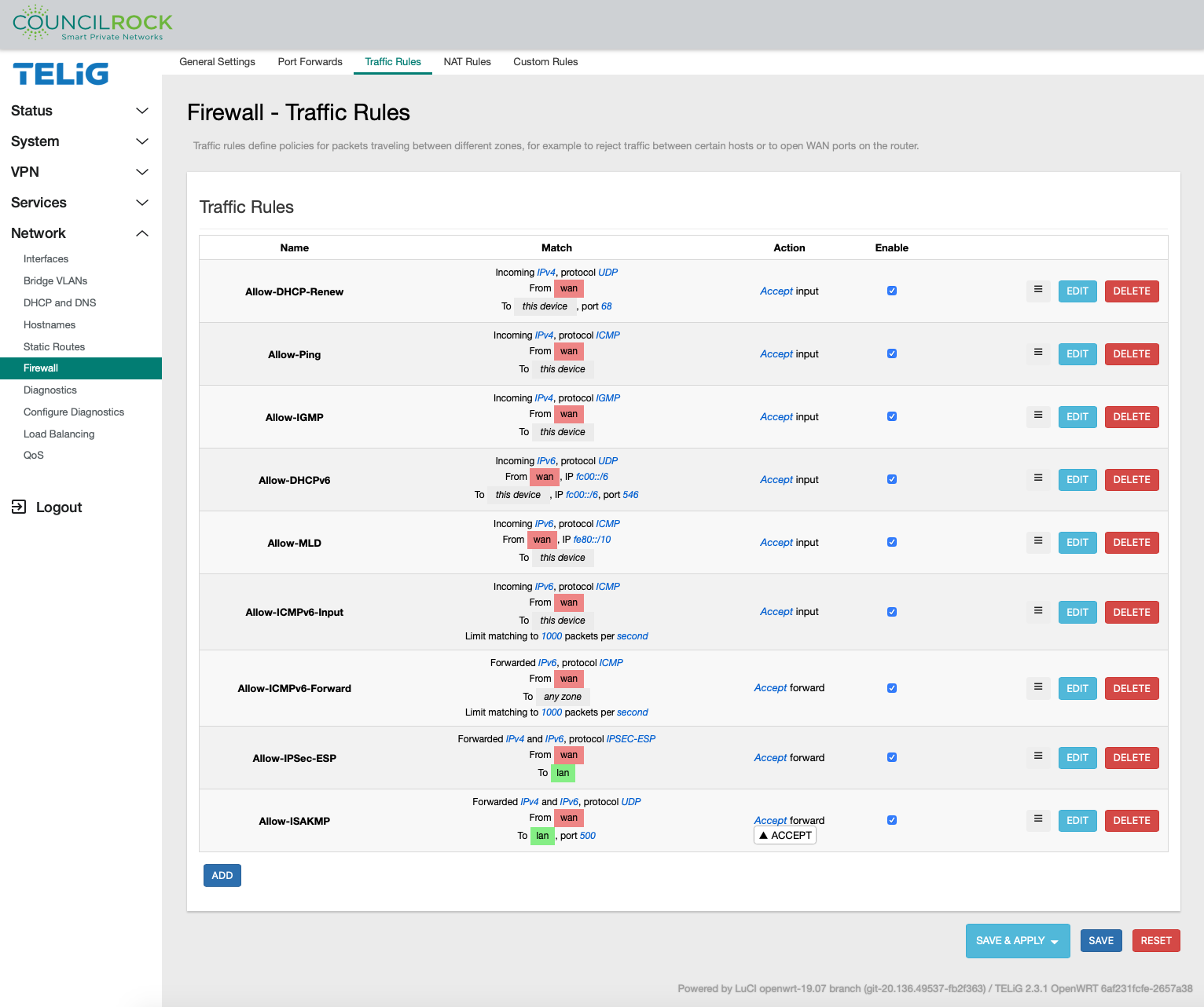 |
When adding / editing an existing Rule, the Firewall - Traffic Rules dialogue is displayed.
Firewall - Traffic Rules > General Settings is provided to configure the Traffic Rule matching criteria:
Protocol
Source zone
Destination zone
IP address and port
And to set the action to take for packets matching the rule.
Available actions are summarized below:
Accept - Allow the traffic to pass the firewall
Reject - Drop the traffic
Don't Track - Do not keep track of traffic
Assign Conntrack Helper - These are modules that can assist the firewall in tracking protocols, intended only for Advanced users.
Apply Firewall / XOR Firewall Mark - Firewall marks provide a powerful mechanism to group services together, intended only for Advanced users
DSCP classification DSCP Marking is used to determine traffic classification for network data. This can be used to determine which network traffic requires higher bandwidth, has a higher priority, and more likely to drop packets. This functionality is intended only for Advanced users
Firewall - Traffic Rules > Advanced Settings provides further restrictions when the traffic rule matches:
Device - select from inbound, outbound, or unspecified
IP address family - restrict to IPv4, IPv6, or both
Source MAC address - select from dropdown list of available MAC addresses
Additional matching configurations - for advanced users
And to pass raw arguments (Firewall Zone Extra IPTables Arguments) to the underlying iptables command.
Important
Firewall Zone Extra IPTables Arguments are intended only for Advanced users.
Firewall - Traffic Rules > Time Restrictions lets the user specify a date and/or time range during which the Traffic Rule will be enforced.
The NAT Rules tab displays existing NAT rules. Here the user can add / delete / edit NAT rules, fine-tuning control over the source IP address(es) used for outbound and forwarded traffic.
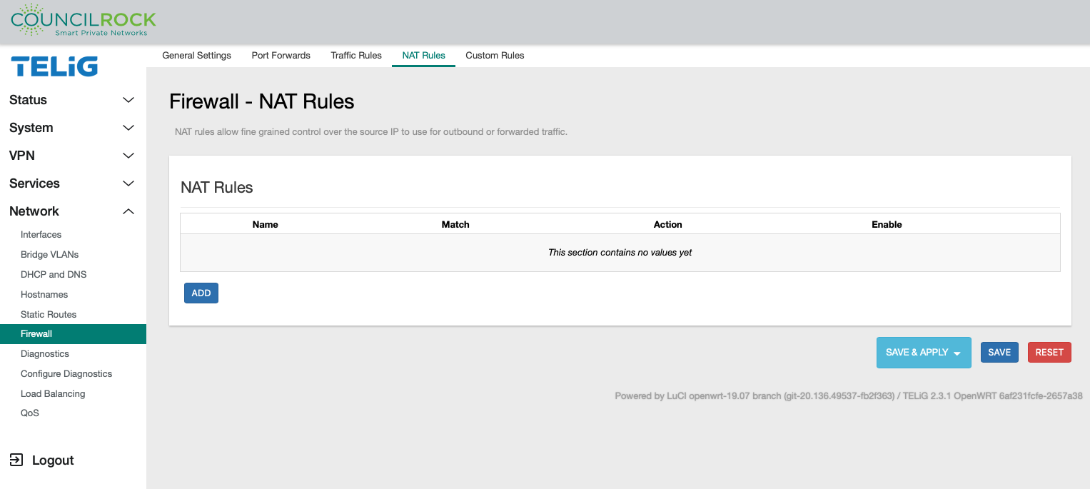 |
When adding a new NAT rule or editing an existing one, the Firewall - NAT Rules dialogue is displayed.
Firewall - NAT Rules > General Settings lets the user set
Protocol
Outbound zone
Source address
Destination address
And the action to take for packets matching the rule. In the case of the SNAT action, you must specify a rewrite IP address.
Firewall - NAT Rules > Advanced Settings lets the user further restrict when the NAT rule is matched by
Outbound device
Additional matching configurations
And to pass raw arguments to the underlying iptables command.
Firewall - NAT Rules > Time Restrictions lets the user specify a date and/or time range during which the Traffic Rule will be enforced.
Important
Firewall NAT Rules are intended only for Advanced users.
The Custom Rules tab lets the user specify a custom shell script to be executed after the default ruleset has been loaded, allowing advanced users direct control to execute arbitrary iptables commands.
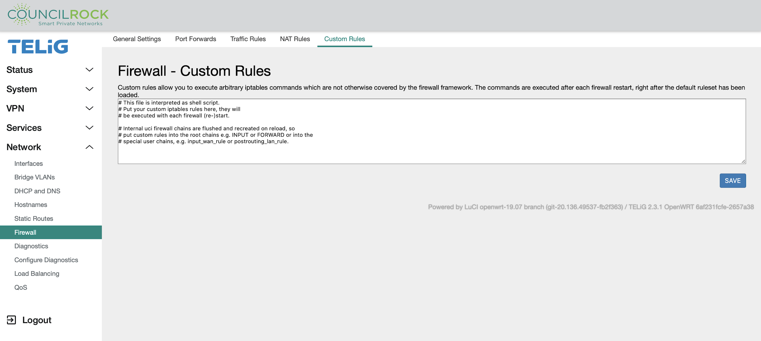 |
Important
Custom Rules are intended only for Advanced users.
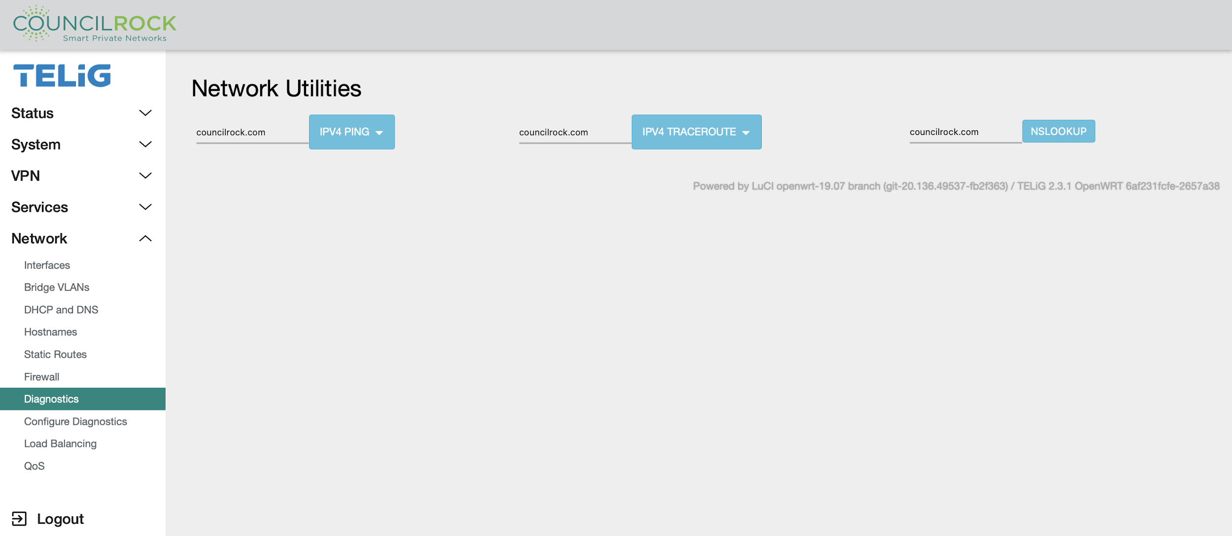
Diagnostics
The Diagnostics menu provides basic tools to verify network state and troubleshoot network issues. Ping, traceroute, or nslookup can be performed on any specified hostname or IP address.
 |
Configure Diagnostics
 |
Note
Out-of-the-box, the E1500 has no modules installed to display in Configure Diagnostics. See Network > Diagnostics for default tools -- ping, traceroute, and nslookup. Use of other diagnostics are intended for advanced users only.
Load Balancing
See Use Case E: Radio Module Failover