Product Details
Description
The E1500 is an edge computing WLAN device that connects end devices to the enterprise network with multiple interface options.
 |
Figure 1: Models E1500-L8N, E1500-8NW
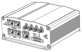 |
Figure 2: Models E1500-LW, E1500-8W
Front & Rear Panels
Front Panel
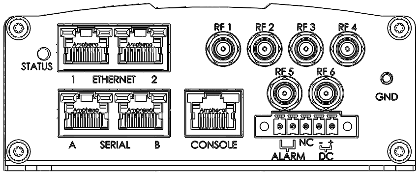 |
E1500-L8N, E1500-8NW
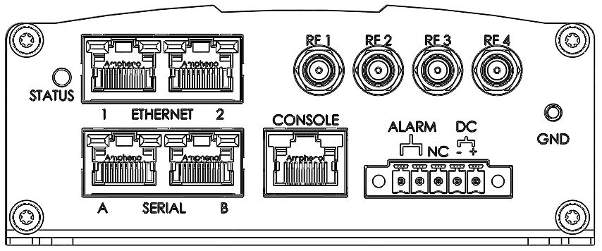 |
E1500-LW, E1500-8W
Top Row
(1) Status LED – System status indicator for LTE models. (LEDs are configurable for non-LTE models - see System > LED Configuration)
Appearance | Status |
|---|---|
Green Blinking (fast) | System Booting |
Red Blinking | System Active, Not joined to radio network |
Green Blinking (slow) | System Active, Joining radio network |
Green Solid | System Active, Joined radio network |
(2) Ethernet 1 / Ethernet 2 Connectors - 10/100/1000 Mbps, Ethernet autodetection
(4) RF Connectors #1-#4
(2) RF Connectors #5-#6 (models E1500-L8N, E1500-8NW)
(1) GND Connector
Models | RF Connectors |
|---|---|
E1500-LW E1500-8W | 4 |
E1500-L8N E1500-8NW | 6 |
E1500 comes with 4 or 6 RF connectors as standard equipment.
RF Ports map to wan interfaces as shown in the table below, where “Main” indicates the primary radio antenna connector, while “Aux” indicates the secondary radio antenna.
RF Port | L8N | LW | 8NW | 8W |
|---|---|---|---|---|
1 | wan_a Main | wan_a Main | wan_b Main | wan_b Main |
2 | wan_a Aux | wan_a Aus | wan_b Aux | wan_b Aux |
3 | wan_c | WiFi CH1 | wan_c LTE | WiFi CH1 |
4 | GPS | GPS | GPS | GPS |
5 | wan_b Main | WiFi CH1 | ||
6 | wan_b Aux | WiFi CH2 |
Bottom Row
(1) SERIAL A Port – RS 232 / RS 485 serial comms, software configurable
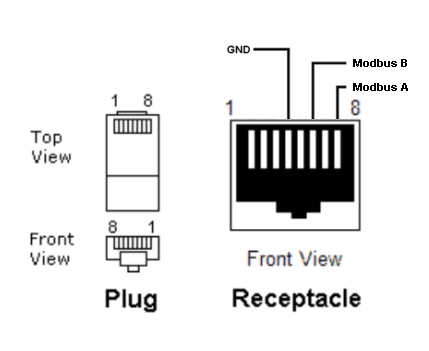
(1) SERIAL B Port – RJ45 – RS 232 serial comms
(1) Console Port – System console serial interface
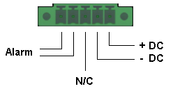
(1) Alarm / Power Connector – Door alarm / tamper sensor input and DC power
Alarm input: the connection is a dry contact, state change monitoring input for a closed loop sensor. An alarm is triggered when the input loop disconnects. A typical use of the input is to attach a door sensor on an enclosure inside of which the unit is mounted; the alarm is triggered when the door is opened. Alarm events are written to the system logs and as an SNMP trap.
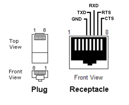
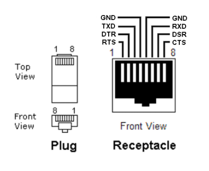
Serial pinouts are given below, and in the table that follows.
 |
 |
 |
Note
In situations where the E1500 is connected to another device using RS232, TXD and RXD are cross connected. RXD on the E1500 (pin 5) connects to TXD on the device. TXD on the E1500 (pin 6) connects to RXD on the device
Note
The pin-outs shown may not match all devices as there is no standard for pin connections or levels for RS232 on 8-pin RJ45 modular connectors. On the RTU connector, the DNP3 over RS485 will depend on the RTU equipment manufacturer's specific pinout.
Pin | RS232 | RS422 | RS485 | RS232 Console |
|---|---|---|---|---|
1 | - | - | - | RTS |
2 | - | - | - | DTR |
3 | - | - | - | TXD |
4 | GND | GND | GND | GND |
5 | RXD | RX + | - | GND |
6 | TXD | TX - | TX/RX - | RXD |
7 | RTS | RX - | - | DSR |
8 | CTS | TX + | TX/RX + | CTS |
 |
Rear Panel
 |
Hardware and Software
Hardware
The E1500 unit consists of two primary circuit boards: A Gateway processor card and a power/interface card. The Power/Interface card includes a wideband DC power supply that converts prime input power into the voltages required for the processor and peripherals. The Power/Interface card also includes circuitry to convert serial data signals into EIA-561 compatible serial via an RJ-45 connector. The unit can be powered through the front panel terminal block connector (9-60VDC) or through 802.3af PoE via Ethernet 1.
The E1500 leverages a dual core ARM Coretex-A9 processor to control all peripherals and run edge intelligence applications. The unit comes standard with 1 GB RAM and 8 GB eMMC flash storage. There are two 10/100/1000 Ethernet ports, two serial, and three peripheral expansion slots.
Three peripheral expansion slots include two mini-PCI express (mPCIe) and one m.2 form factor. A variety of cards are commercially available to enable communications over a wide range of interfaces.
The i.MX6 ARM Cortex-A9 processor is used to connect the serial and Ethernet ports to peripherals placed in these expansion slots. The Gateway processor card also includes onboard GPS, a gyro, and encryption co-processor.
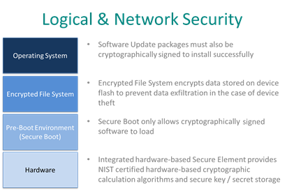
Software
The E1500 unit is based on the OpenWRT Linux operating system. The operating system runs on top of a secure file system that includes secure boot and encryption.
 |
The device comes configured with a suite of tools and services to enable Distribution Automation (DA), Smart Networking, and Network Function Virtualization.
The software supports an edge intelligence framework that can run 3rd party applications. The Linux operating system is customized with advanced features to enable secure resource allocation and isolation, which provide the foundation for containerizing these applications.
Accessories and Model Options
Accessories
A range of accessories are available including connectors, mounting, antennas, and more. Contact your sales representative at sales@councilrock.com for more information.
Model options
All E1500s include Public/Private LTE.
Optional communications include LTE-CBRS, LTE Cat-M/NB-IoT, Private Enterprise Broadband 900MHz 3+3MHz FDD, and 2.5/5 GHz WiFi. See Model Options Table for specifics.