Appendix B
Use Cases
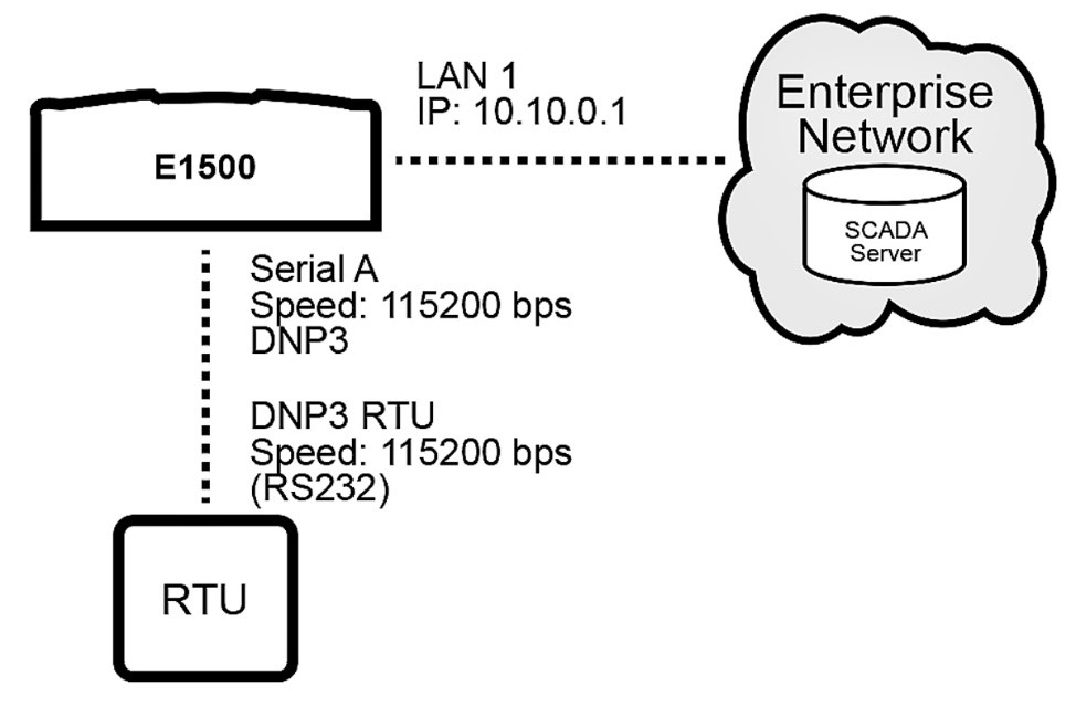
Use Case A: Serial Connection via WAN
Example: Connect the E1500 to a device via serial / RS232 with DNP and send device traffic to the Enterprise Network through WAN A
Requirements: Fundamentals C: WAN Interface Configuration
 |
Procedure:
Navigate to Services > Serial Gateways and set configuration for Serial A
Protocol: RS232
Gateway: DNP3
Baud Rate: 115200
Parity: None
Data Bits: 8
Stop Bits: 1
TCP Port: 20000
TCP Listener Enabled: check
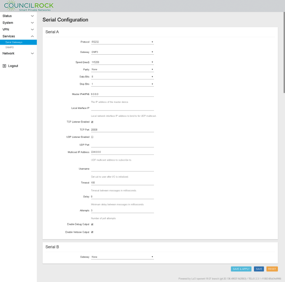
Master IPV4/IPV6: IP address of the master device. The master device is the device that polls the end devices or “slaves”
TCP Listener Disabled: If checked, the device does not open the defined TCP port to listen for connections
UDP Listener Disabled: If checked, the device does not open the defined UDP port to listen for connections
Multicast IP address: Enter here the multicast IP address to subscribe to in case the DNP master is configured to send UDP multicast messages to a group of slave devices
Local Interface IP: Local network Interface for sending multicast messages
Username: The user to execute the application in the OS of the device. Be sure the username entered has administrative privileges; “root” for example.
Note
To configure the gateway for Modbus, select Gateway: Modbus. Set the IP address of the Modbus Host at "Modbus Host Address." Be sure to set the "Master IPv4/IPv6" IP address to the unit's IP address. This opens the socket on port 502, allowing Modbus communication.
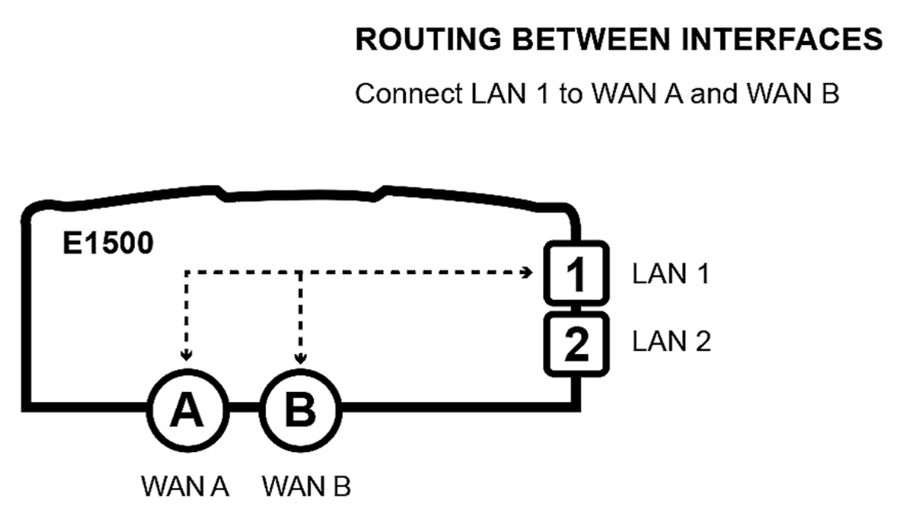
Use Case B: LAN to WAN Traffic
Example: Configure the E1500 to route traffic between radio ports (WAN A / WAN B) and ethernet port (LAN 1) as shown below. Set WAN load balancing to WAN A 60% / WAN B 40%.
Requirements:
Fundamentals B: LAN Interface config
Fundamentals C: WAN Interface config
 |
Procedure:
Set up the LAN to WAN firewall zone:
Navigate to Network > Firewall > General Settings
Under Zones, click ADD and set the following (see figure below)
Name: lan
Input / Output / Forward: accept
Covered Networks: select available lan(s) to include in this zone (Input / output / forward fields set the default policies for traffic entering and leaving the firewall zone
Click SAVE
Figure 107. Firewall Zone Settings: lan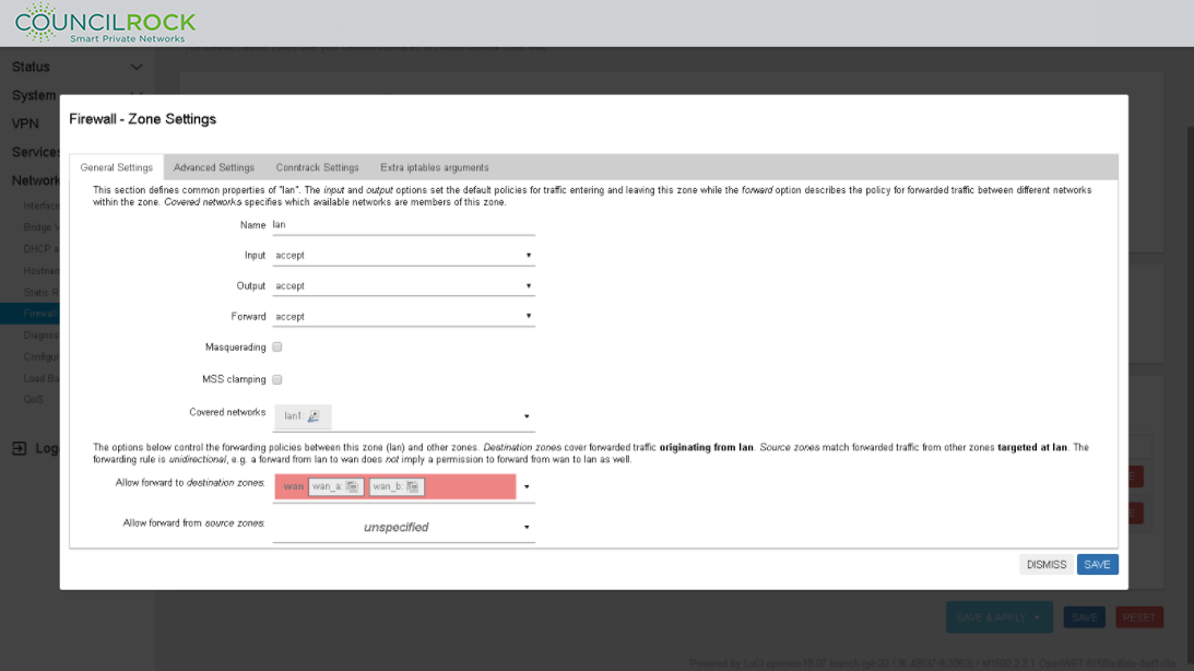
Set up Load Balancing
Configure Interfaces
Navigate to Network > Load Balancing: Interfaces
Add / Select the MWAN Interface for wan_a and set up as shown below
Enabled: checked
Initial State: Online
Internet Protocol: IPv4
Tracking method: ping
Tracking hostname or IP address:
Enter the hostname or IP address of the node to ping to determine if the link is up or down
Leaving this blank assumes the interface is always online
Note
Tracking IP address 8.8.8.8 (Google's DNS server) is provided as an example. Use an IP address or hostname appropriate for your networking scheme.
Tracking reliability: 1
Ping count: 1
Ping size: 56
Max TTL: 60
Check link quality: unchecked
Ping timeout: 2 sec
Ping interval: 5 sec
Failure interval: 5 sec
Keep failure interval: unchecked
Recovery interval: 5 sec
Interface down: 3
Interface up: 3
Flush conntrack table: all unchecked
Metric: this is not an input, just for display
Click SAVE & APPLY
Click the Interfaces Tab to return to the MWAN - Interfaces view and repeat the setup for wan_b
Figure 108. MWAN Interface: wan_a Load Balancing configuration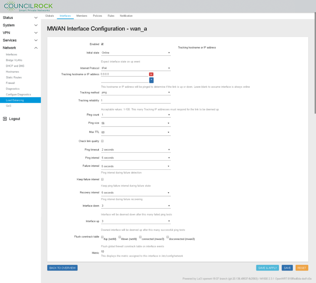
Configure MWAN Members with Load Balancing settings
Navigate to the Members Tab
On the text input line next to the ADD button and enter "wan_a_main" (In this example we use wan_a_main to indicate the high priority member for load balancing and wan_a_secondary to indicate the low priority member for load balancing)
Click ADD to open the MWAN Member Configuration window for wan_a_main. Enter the following settings (See figure below: Member Configuration to set Load Balancing (Weight) on wan_a)
Next to "Interface" click on - - Please choose - - and select wan_a
Metric = 1 (Metric is used as a sorting measure. If a packet that is about to be routed fits two rules, the one with the lower metric is applied)
Weight = 60 (load balance percent)
Click SAVE & APPLY, then BACK TO OVERVIEW
Repeat the step above, adding a new member "wan_b_secondary" (See figure below: Member Configuration to set Load Balancing (Weight) on wan_b)
Interface: wan_b
Metric = 1
Weight = 40
Click SAVE & APPLY followed by BACK TO OVERVIEW
MWAN Members window displays the load balancing scheme (see figure below: Member Configuration summarizing Members Load Balancing
Figure 109. Member Configuration to set Load Balancing (Weight) on wan_a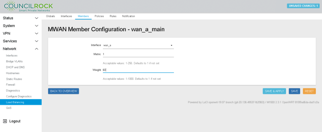 Figure 110. Member Configuration to set Load Balancing (Weight) on wan_b
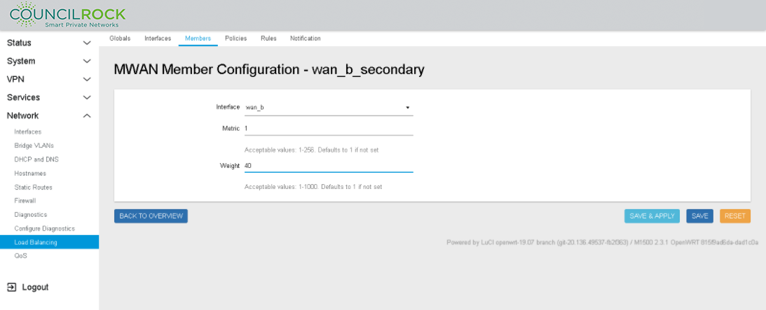 Figure 111. Member Configuration summarizing Members Load Balancing
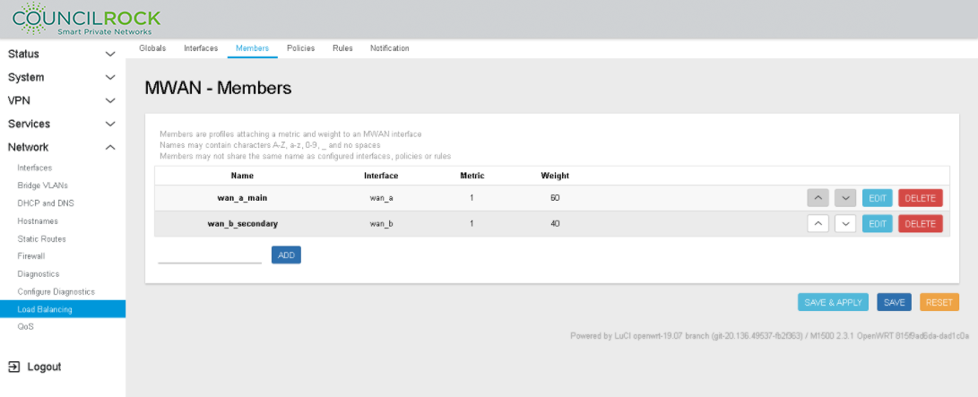
Add a Load Balancing Policy
Navigate to the Policies Tab
On the text input line next to the ADD button enter "main_policy"
Click ADD to open the MWAN Policy Configuration window for main_policy
Next to "Member Used" click on - - Please choose - - and select wan_a_main (See figure below: Load Balancing Policy Configuration: Member selection)
Repeat to select wan_b_secondary
Last resort: unreachable (reject) - this is the default setting
Click SAVE & APPLY then BACK TO OVERVIEW
MWAN Policy displays the Policy (see figure below: Load Balancing Policy Configuration: Policy settings)
Figure 112. Load Balancing Policy Configuration: Member selection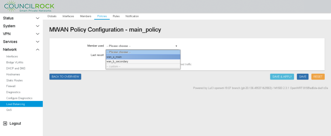 Figure 113. Load Balancing Policy Configuration: Policy settings
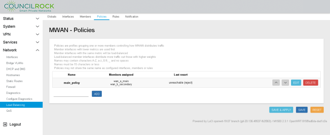
Add a Load Balancing Rule to the Load Balancing Policy
Navigate to the Rules Tab
On the text input line next to the ADD button and enter "wan_a_rule"
Click ADD to open the MWAN Rule Configuration window for wan_a_rule (See figure below: Load Balancing Rule Configuration using Load Balancing Policy)
Source address: 10.0.0.1/24
Policy assigned: main_policy
All other fields use the default settings for this example
Click SAVE & APPLY then BACK TO OVERVIEW
MWAN - Rules displays the Policy (See figure below: Load Balancing Rule Summary using Load Balancing Policy)
Figure 114. Load Balancing Rule Configuration using Load Balancing Policy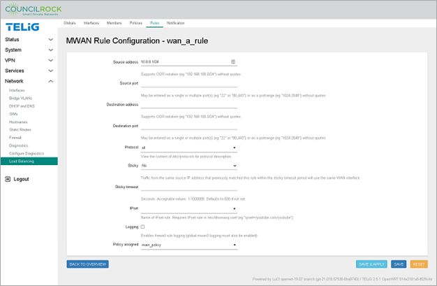 Figure 115. Load Balancing Rule Summary using Load Balancing Policy
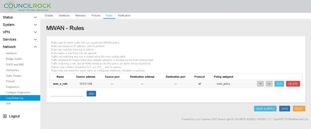
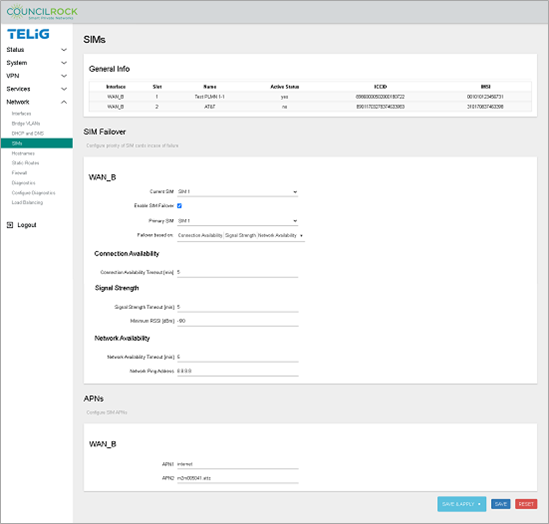
Use Case C: SIM Failover
Example: Configure the E1500 to switch between SIM cards based on signal quality above -90dBm or network connectivity. Check connectivity every 5 minutes.
Note
SIM Failover is only available on dual-SIM units. The menu options shown in this section are not available on single-SIM units. See Model Options.
When the primary SIM card’s network fails, the interface switches to the secondary SIM card. Network failure is tested against any of the following conditions:
Network connectivity
RSSI threshold criteria (-90dBm in the example)
IP ping tests to a device
Criteria are tested at regular intervals (5 min in the example). Note that different intervals can be set for different criteria depending on user needs & preferences.
Requirements: Fundamentals B: LAN Interface config
Procedure:
Navigate to Network > SIMs and note the interface name, slot numbers, and names of SIM cards in the unit.
In the SIM Failover section, check "Enable SIM Failover" to show failover options.
Current SIM: The SIM that is currently active. With or without a failover configuration, the user can set the active SIM here.
Primary SIM: The SIM that is primary for failover purposes.
in the dropdown next to Failover based on, select all three options
Connection Availability
Signal Strength
Network Availability
Set Connection Availability criteria
Connection Availability Timeout [min]: 5
Set Signal Strength criteria
Signal Strength Timeout [min]: 5
Minimum RSSI [dBm]: -90
Set Network Availability criteria
Network Availability Timeout [min]: 5
Network Ping Address: 8.8.8.8
Note
Network Ping Address shown here is for example only. An appropriate Ping Address for your network deployment should be entered here.
Note
After a primary SIM failover event, the 'non-primary' SIM becomes the Current SIM. The user can reset the failover by manually switching the Current SIM back to primary.
 |
Use Case D: Radio Module Failover
The network balancing feature of the E1500 allows outbound WAN interface traffic to be load balanced over multiple WAN interfaces based on a numeric weight assignment. The user can also configure interfaces as main/backup WANs.
The user can configure the device to monitor each WAN connection using repeated ping tests thus allowing the device to automatically route traffic to another WAN interface if the main WAN interface loses connectivity.
Example: Configure the device to perform automatic radio module failover from a main WAN interface to a backup WAN interface
Requirements: Fundamentals C: WAN Interface config
Procedure:
Navigate to Network > Load Balancing > Interfaces
Add WAN interfaces. Be mindful that the names of WAN interfaces you are going to add must match the WAN interface names in the Network > Interfaces menu. Names are case sensitive. For this example, we use "wan_a" and "wan_b".
Configure wan_a as described below. Generally, the default values are used; only the Tracking hostname or IP address needs to be entered.
Note
In some scenarios the "Tracking hostname or IP address" may need to be changed. For example, if wan_a is connected to a network with no internet access, IP 8.8.8.8 might not be reachable, therefore a different IP address must be configured as the tracking IP.
wan_a configuration:Enabled: checked
Initial State: Online
Internet Protocol: IPv4
Tracking hostname or IP address: 8.8.8.8 (For demo purposes, we use Google's DNS server)
Tracking method: ping
Tracking reliability: 1
Ping count: 1
Ping size: 56
Max TTL: 60
Check link quality: uncheck
Ping Timeout: 2
Ping interval: 5
Failure interval: 5
Keep failvure interval: uncheck
Recovery interval: 5
Interface down: 3
Interface up: 3
Flush conntrack table: uncheck all
ifup
ifdown
connected
disconnected
Metric: this value is for display only, no data to enter
Figure 117. Network > Load Balancing > Interfaces (input screen)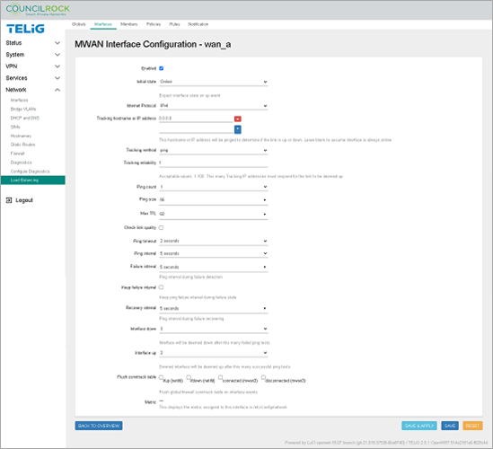 Figure 118. Network > Load Balancing > Interfaces (interface summary screen)
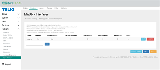
Click SAVE to create load balancing interface "wan_a"
Repeat steps 1 through 4 for interface wan_b
Figure 119. WAN Interfaces are set up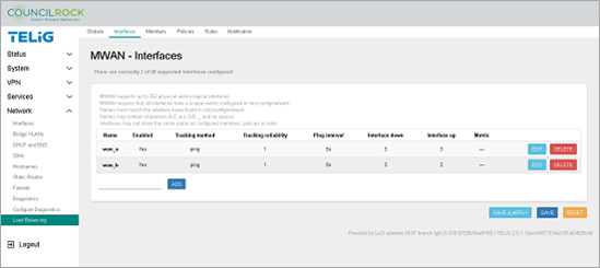
Navigate to Network > Load Balancing > Members.
Add a member for wan_a, the main interface in this example.
On the text input line to the left of the ADD button, enter "failover_wan_a" and click ADD
Enter Metric = 1
Enter Weight = 1
Click the SAVE & APPLY button, followed by the BACK TO OVERVIEW button.
Repeat steps 6-7 to create "failover_wan_b", the backup interface in this example. Set Metric and Weight = 2.
Figure 120. Member Configuration - failover_wan_a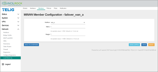 Figure 121. Member Configuration - failover_wan_b
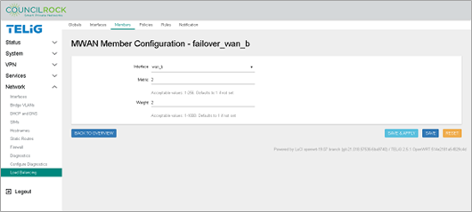 Figure 122. Load Balancing Members are set up
Create the Load Balancing Policy. The policy sets the unit to reject traffic across interfaces that are down.
Navigate to the Policies tab.
Click on the text input line next to the ADD button, and enter "test_policy".
From the Member used dropdown, select both "failover_wan_a" and "failover_wan_b".
Use the default setting for Last Resort: unreachable (reject).
Click the SAVE & APPLY button, followed by the BACK TO OVERVIEW button.
Figure 123. Network > Load Balancing > Policies (add a policy)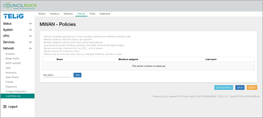 Figure 124. Network > Load Balancing > Policies (define a policy)
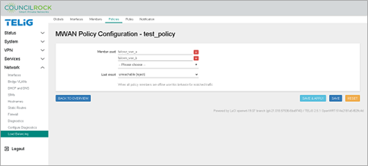
Create Load Balancing Rules. Rules determine what traffic uses the Load Balancing Policy defined in the previous step. In our example all traffic to the WAN will be part of the load balancing policy. Here we set up all incoming traffic (to the default route 0.0.0.0/0) to be our rule "classifier."
Navigate to the Rules tab
In the text input line next to the ADD button, enter "test_rule" and click the ADD button.
Configure test_rule as described below. Generally, the default values are used, only the Destination address and the Policy assigned needs to be entered.
test_rule configurationSource address: blank
Source port: blank
Destination address: 0.0.0.0/0
Destination port: blank
Protocol: all
Sticky: No
Sticky timeout: blank
IPset: blank
Logging: unchecked
Policy Assigned: test_policy (the policy from the previous step will be available in the dropdown list)
Figure 125. Network > Load Balancing > Rules (define a rule)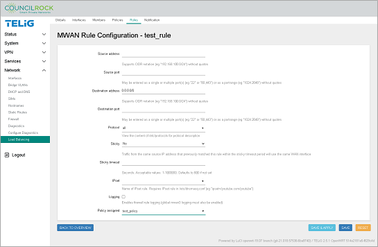
Click the SAVE & APPLY button
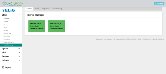
Verifying the configuration:
Creating the rule is the final step in this configuration. To verify the configuration is functioning, navigate to Status > Load Balancing > Interface. Verify that both MWAN interfaces (wan_a and wan_b) display "Status: Online." Note that interface uptime is provided here.
 |
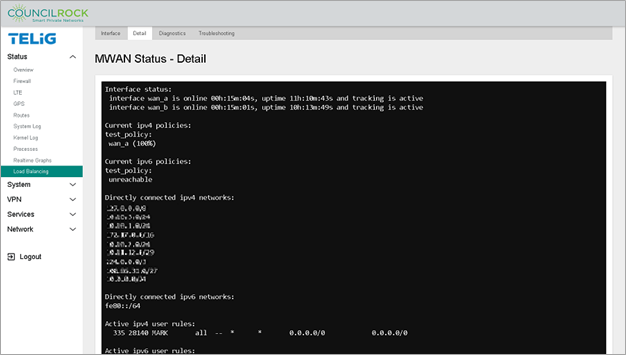
Additionally, on the Detail tab, we see the test_policy is directing 100% of traffic to wan_a, the interface we defined with the lowest metric.
 |
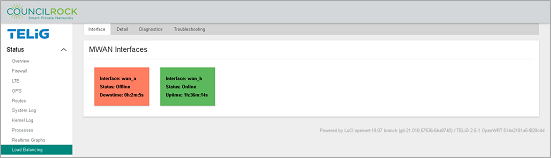
To validate that the failover is set up correctly, disable the main interface by navigating to Network > Interfaces and clicking the STOP button on wan_a. Navigate back to Status > Load Balancing > Detail to verify that traffic has switched to the backup interface “wan_b”.
 |
 |
Use Case E: Interface Bridging
The LAN bridge combines the WLAN interface(s) with the wired LAN ports to create a single logical network.
Example: Configure a bridge between Ethernet ports lan1 and lan2.
Requirements:
Fundamentals B: LAN Interface config
Fundamentals C: WAN Interface config
Procedure:
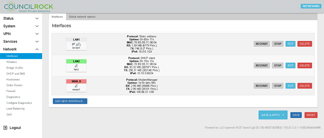
Navigate to Network > Interfaces and click the EDIT button on LAN1
Figure 130. Network > Interfaces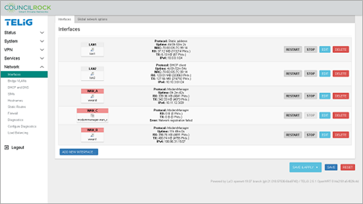
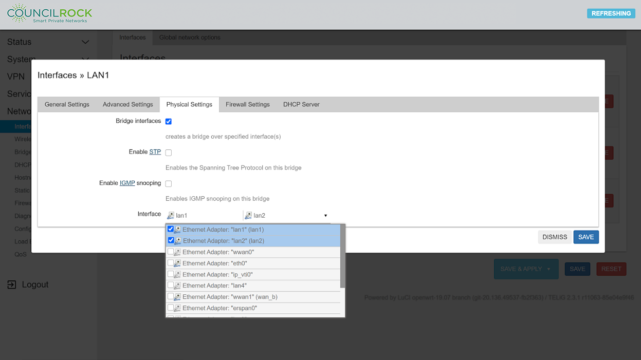
Select the 'Physical Settings' tab and select the 'Bridge interface' checkbox. In the dropdown menu under 'Interfaces' select lan1 and lan2
Click the SAVE button to close the edit window
Click the SAVE & APPLY button to apply changes
All LAN physical ports in the bridge will act as a single network.
 |
 |
Use Case F: SNMPD Trap Alerts
Example: Send traps to a SNMP server using SNMPV2
Procedure:
Navigate to Services > SNMPD
Figure 133. Services > SNMPD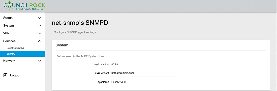
Scroll down to the "v2c Traps" section and click the ADD button to open the lines for text input. Enter the required information:
Host: IP address of the SNMP server
Community: SNMP community string to use when sending traps to the server. This community needs to match the community on the server side.
Port: Port on the SNMP server that will be receiving the traps.
Figure 134. Services > SNMPD: v2c Traps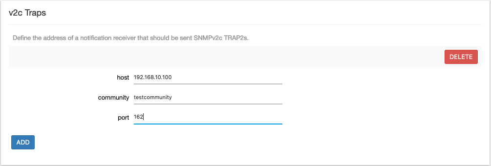
Click the SAVE & APPLY button.